< Previous | Contents | Next >
The Texture node
Texture Node Introduction
NOTE: Background pixels may have U and V values of 0.0, which set those pixels to the color of the texture’s corner pixel. To restrict texturing to specific objects, use an effect mask based on the Alpha of the object or its Object or Material ID channel.
NOTE: Background pixels may have U and V values of 0.0, which set those pixels to the color of the texture’s corner pixel. To restrict texturing to specific objects, use an effect mask based on the Alpha of the object or its Object or Material ID channel.
NOTE: Background pixels may have U and V values of 0.0, which set those pixels to the color of the texture’s corner pixel. To restrict texturing to specific objects, use an effect mask based on the Alpha of the object or its Object or Material ID channel.
The Texture node controls the texture mapping of elements in a rendered image. The Texture node relies on the presence of U and V Map channels in a 3D-rendered image connected to the main Image input. If these channels are not present, this node has no effect.
Inputs
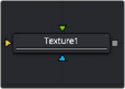
The Texture node includes three inputs: one for the main image with UV map channels, one for a texture map image, and another for an effect mask to limit the area where the replace texture is applied.
![]()
— Input: This orange input accepts a 2D image that includes UV channels. If the UV channels are not in the images, this node has no effect.
— Texture: The green texture map input provides the texture that is wrapped around objects, replacing the current texture.
— Effect Mask: The optional blue effect mask input accepts a mask shape created by polylines, basic primitive shapes, paint strokes, or bitmaps from other tools. Connecting a mask to this input limits the texture to only those pixels within the mask. An effects mask is applied to the tool after the tool is processed.
Basic Node Setup
The Texture node is inserted after a 2D image that contains a Texture UV channel. Below, a Renderer 3D is used to add texture coordinates to 3D text. The Texture node can then be used to manipulate those coordinates using a new texture connected to the green texture input.
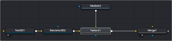
A Texture node used to manipulate the texture coordinates and add texture to a Text 3D node
Inspector
Texture controls
Texture Tab
![]()
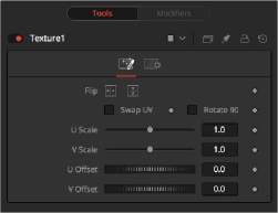
The Texture tab controls allow you to flip, swap, scale, and offset the UV texture image connected to the texture input.
Use these two buttons to flip the texture image horizontally and/or vertically.
When this checkbox is selected, the U and V channels of the source image are swapped.
The texture map image is rotated 90 degrees when this checkbox is enabled.
These controls change the scaling of the U and V coordinates used to map the texture. Changing these values effectively enlarges and shrinks the texture map as it is applied.
Adjust these controls to offset the U and V coordinates. Changing the values causes the texture to appear to move along the geometry of the object.