< Previous | Contents | Next >
})
as well as for the actual values:
local rates = { 24, 25, 30, 48, 50, 60 }
Define an offset from the starting frame of the current comp.
Verbose output of the Timecode/Frame value in the Console.
The Timecode/Frames conversion is done according to the FPS settings. The result might look like this:
TimeCode: 00:00:08:15
Frames: 207
Common Controls
The Settings tab in the Inspector is also duplicated in other Metadata nodes. These common controls are described in detail in the following “The Common Controls” section.
The Common Controls
Nodes that handle metadata operations share several identical controls in the Inspector. This section describes controls that are common among Metadata nodes.
![]()
Inspector
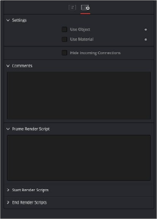
The Common Metadata Settings tab
Settings Tab
The Settings tab in the Inspector can be found on every tool in the Metadata category. The controls are consistent and work the same way for each tool.
Some 3D software can render to file formats that support additional channels. Notably, the EXR file format supports Object ID and material ID channels, which can be used as a mask for the effect. These checkboxes determine whether the channels are used, if present. The specific Material ID or Object ID affected is chosen using the next set of controls.
This checkbox appears only when the Use Object or Use Material checkboxes are selected. It toggles the method used to deal with overlapping edges of objects in a multi-object image. When enabled, the Coverage and Background Color channels are used to separate and improve the effect around the edge of the object. If this option disabled (or no Coverage or Background Color channels are available), aliasing may occur on the edge of the mask.
For more information on the Coverage and Background Color channels, see Chapter 78, “Understanding Image Channels,” in the DaVinci Resolve Reference Manual, or Chapter 16 in the Fusion Reference Manual.
Use these sliders to select which ID is used to create a mask from the object or material channels of an image. Use the Sample button in the same way as the Color Picker: to grab IDs from the image displayed in the view. The image or sequence must have been rendered from a 3D software package with those channels included.
![]()
The Comments field is used to add notes to a tool. Click in the empty field and type the text. When a note is added to a tool, a small red square appears in the lower-left corner of the node when the full tile is displayed, or a small text bubble icon appears on the right when nodes are collapsed. To see the note in the Node Editor, hold the mouse pointer over the node to display the tooltip.
Three Scripting fields are available on every tool in Fusion from the Settings tab. They each contain edit boxes used to add scripts that process when the tool is rendering. For more details on scripting nodes, please consult the Fusion scripting documentation.