< Previous | Contents | Next >
The Custom Tool node
Custom Tool Node Introduction
The Custom Tool node is the most complex and the most powerful node in Fusion. It is used to create custom expressions and filters to modify an image. In addition to providing three image inputs, the Custom Tool node allows for the connection of up to eight numeric inputs and as many as four XY position values from other controls and parameters in the node tree.
Per-pixel calculations can be performed on the Red, Green, Blue, Alpha, Z, Z-Coverage, UV texture coords, XYZ Normals, RGBA background color, and XY motion vector channels of the images.
You should be moderately experienced with scripting, or C++ programming, to understand the structure and terminology used by the Custom Tool node.
Inputs
The Custom Tool node has three image inputs, a matte input, and an effect mask input.
![]()
— Input: The orange, green, and magenta inputs combine 2D images to make your composite. When entering them into the Custom Tool fields, they are referred to as c1, c2 and c3 (c standard for all three R, G, B channels)
— Matte Input: The white input is for a matte created by polylines, basic primitive shapes, paint strokes, or bitmaps from other tools. Connecting a matte to this input allows a matte to be combined into any equation. When entering the matte into the Custom Tool fields, it is referred to as m1.
— Effect Mask: The blue input is for a mask shape created by polylines, basic primitive shapes, paint strokes, or bitmaps from other tools. Connecting a mask to this input limits the Custom Tool effect to only those pixels within the mask.
Basic Node Setup
The Custom Tool below takes two image inputs and a matte input, and then combines them using some calculation. The result can be output to a Merge or other image-processing nodes.
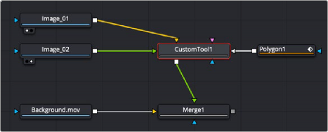
A Custom Tool is used to build your own effects using C++ and scripting.
Inspector
![]()
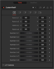
The Custom Tool Controls tab
Controls Tab
These four controls are 2D X and Y center controls that are available to expressions entered in the Setup, Intermediate, and Channels tabs as variables p1x, p1y, , p4x, p4y. They are normal positional
controls and can be animated or connected to modifiers as any other node might.
The values of these controls are available to expressions entered in the Setup, Intermediate, and Channels tabs as variables n1, n2, n3, , n8. They are normal slider controls and can be animated or
connected to modifiers exactly as any other node might.
The Custom Tool node provides 4 LUT splines. The values of these controls are available to expressions entered in the Setup, Intermediate, and Channels tabs using the getlut# function. For example, setting the R, G, B, and A expressions to getlut1(r1), getlut2(g1), getlut3(b1), and getlut4(a1), respectively, would cause the Custom Tool node to mimic the Color Curves node.
These controls can be renamed using the options in the Config tab to make their meanings more apparent, but expressions still see the values as n1, n2, ..., n8.
Custom Tool Setup Tab
![]()
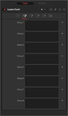
The Custom Tool Setup tab

NOTE: Because these expressions are evaluated once per frame only and not for each pixel, it makes no sense to use per-pixel variables like X and Y or channel variables like r1, g1, b1. Allowable values include constants, variables such as n1..n8, time, W and H, and functions like sin() or getr1d().
NOTE: Because these expressions are evaluated once per frame only and not for each pixel, it makes no sense to use per-pixel variables like X and Y or channel variables like r1, g1, b1. Allowable values include constants, variables such as n1..n8, time, W and H, and functions like sin() or getr1d().
NOTE: Because these expressions are evaluated once per frame only and not for each pixel, it makes no sense to use per-pixel variables like X and Y or channel variables like r1, g1, b1. Allowable values include constants, variables such as n1..n8, time, W and H, and functions like sin() or getr1d().
Up to four separate expressions can be calculated in the Setup tab of the Custom Tool node. The Setup expressions are evaluated once per frame before any other calculations are performed. The results are then made available to the other expressions in the Custom Tool node as variables s1, s2, s3, and s4.
Custom Tool Intermediate Tab
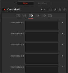
The Custom Tool Intermediate tab
An additional four expressions can be calculated in the Inter tab. The Inter expressions are evaluated once per pixel after the Setup expressions are evaluated but before the Channel expressions are evaluated. Per-pixel channel variables like r1, g1, b1, and a1 are allowable. Results are available as variables i1, i2, i3, and i4.
![]()
Custom Tool Config Tab
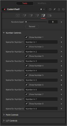
The Custom Tool Config tab
Use this to set the seed for the rand() and rands() functions. Click the Randomize button to set the seed to a random value. This control may be needed if multiple Custom Tool nodes are required with different random results for each.
There are eight sets of Number controls, corresponding to the eight Number In sliders in the Controls tab. Uncheck the Show Number checkbox to hide the corresponding Number In slider, or edit the Name for Number text field to change its name.
There are four sets of Point controls, corresponding to the four Point In controls in the Controls tab. Uncheck the Show Point checkbox to hide the corresponding Point In control and its crosshair in the viewer. Similarly, edit the Name for Point text field to change the control’s name.
Custom Tool Channels Tab
![]()
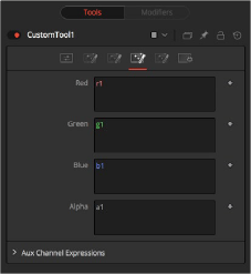
The Custom Tool Channel tab
The Channel tab is used to set up one expression per each available channel of the image. Each expression is evaluated once per pixel. The result creates the value for that pixel in the output of the image.
Color Channel expressions (RGBA) should generally return floating-point values between 0.0 and 1.0. Values beyond this are clipped if the destination image is an integer. Other expression fields should produce values appropriate to their channel (e.g., between -1.0 and 1.0 for Vector and Normal fields, 0.0 to 1.0 for Coverage, or any value for Depth). The Channel expressions may use the results from both the Setup expressions (as variables s1–s4) and Inter expressions (as variables i1–i4).

NOTE: Use w and h and ax and ay without a following number to get the dimensions and aspect of the primary image.
NOTE: Use w and h and ax and ay without a following number to get the dimensions and aspect of the primary image.
NOTE: Use w and h and ax and ay without a following number to get the dimensions and aspect of the primary image.
![]()
Custom Tool Node Syntax
Value Variables | |
n1..n8 | Numeric Inputs |
p1x..p4x | Position Values (X-axis) |
p1y..p4y | Position Values (Y-axis) |
s1..s4 | Setup Expression Results |
i1..i4 | Inter Expression Results |
time | Current Frame |
x | Horizontal co-ordinate of the current pixel, between 0.0 and 1.0 |
y | Vertical co-ordinate of the current pixel, between 0.0 and 1.0 |
w (or w1..w3) | Width of Image (for image1..image3) |
h (or h1..h3) | Height of Image (for image1..image3) |
ax (or ax1..ax3) | Image Aspect X (for image1..image3) |
ay (or ay1..ay3) | Image Aspect Y (for image1..image3) |
Channel (Pixel) Variables | |
c1..c3 | Current Channel (for image1..image3) |
r1..r3 | Red (for image1..image3) |
g1..g3 | Green (for image1..image3) |
b1..b3 | Blue (for image1..image3) |
a1..a3 | Alpha (for image1..image3) |
z1..z3 | Z-Buffer (for image1..image3) |
cv1..cv3 | Z Coverage (for image1..image3) |
u1..u3 | U Coordinate (for image1..image3) |
v1..v3 nx1..nx3 | V Coordinate (for image1..image3) X Normal (for image1..image3) |
ny1..ny3 | Y Normal (for image1..image3) |
nz1..nz3 | Z Normal (for image1..image3) |
bgr1..bgr3 | Background Red (for image1..image3) |
bgg1..bgg3 | Background Green (for image1..image3) |
bgb1..bgb3 | Background Blue (for image1..image3) |
bga1..bga3 | Background Alpha (for image1..image3) |
vx1..vx3 | X Vector (for image1..image3) |
Channel (Pixel) Variables | |
vy1..vy3 | Y Vector (for image1..image3) |
nz1..nz3 | Z Normal (for image1..image3) |

NOTE: Use c1, c2, c3 to refer to the value of a pixel in the current channel. This makes copying and pasting expressions easier. For example, if c1/2 is typed as the red expression, the result would be half the value of the red pixel from image 1, but if the expression is copied to the blue channel, now it would have the value of the pixel from the blue channel.
NOTE: Use c1, c2, c3 to refer to the value of a pixel in the current channel. This makes copying and pasting expressions easier. For example, if c1/2 is typed as the red expression, the result would be half the value of the red pixel from image 1, but if the expression is copied to the blue channel, now it would have the value of the pixel from the blue channel.
NOTE: Use c1, c2, c3 to refer to the value of a pixel in the current channel. This makes copying and pasting expressions easier. For example, if c1/2 is typed as the red expression, the result would be half the value of the red pixel from image 1, but if the expression is copied to the blue channel, now it would have the value of the pixel from the blue channel.
To refer to the red value of the current pixel in input 1, type r1. For the image in input 2, it would be r2.
— get[ch][#]b(x, y) Read pixel at x,y, or 0 if out of bounds—e.g., getr1b(0,0)
— get[ch][#]d(x, y) Read pixel at x,y or edge pixel if out of bounds—e.g., getr1d(0,0)

NOTE: There are a variety of methods used to refer to pixels from locations other than the current one in an image.
NOTE: There are a variety of methods used to refer to pixels from locations other than the current one in an image.
NOTE: There are a variety of methods used to refer to pixels from locations other than the current one in an image.
— get[ch][#]w(x, y) Read pixel at x,y or wrap if out of bounds—e.g., getr1w(0,0)
![]()
In the above description, [ch] is a letter representing the channel to access. The [#] is a number representing the input image. So to get the red component of the current pixel (equivalent to r), you would use getr1b(x,y). To get the alpha component of the pixel at the center of image 2, you would use geta2b(0.5, 0.5).
— getr1b(x,y) Output the red value of the pixel at position x, y, if there were a valid pixel present. It would output 0.0 if the position were beyond the boundaries of the image (all channels).
— getr1d(x,y) Output the red value of the pixel at position x, y. If the position specified were outside of the boundaries of the image, the result would be from the outer edge of the image (RGBA only).
— getr1w(x,y) Output the red value of the pixel at position x, y. If the position specified were outside of the boundaries of the image, the x and y coordinates would wrap around to the other side of the image and continue from there (RGBA only).
To access other channel values with these functions, substitute the r in the above examples with the correct channel variable (r, g, b, a and, for the getr1b() functions only, z, and so on), as shown
above. Substitute the 1 with either 2 or 3 in the above examples to access the images from the other image inputs.
Mathematical Expressions | |
pi | The value of pi |
e | The value of e |
log(x) | The base-10 log of x |
ln(x) | The natural (base-e) log of x |
sin(x) | The sine of x (x is degrees) |
cos(x) | The cosine of x (x is degrees) |
tan(x) | The tangent of x (x is degrees) |
asin(x) | The arcsine of x, in degrees |
acos(x) | The arccosine of x, in degrees |
atan(x) | The arctangent of x, in degrees |
atan2(x,y) | The arctangent of x,y, in degrees |
abs(x) | The absolute (positive) value of x |
int(x) | The integer (whole) value of x |
frac(x) | The fractional value of x |
sqrt(x) | The Square Root of x |
rand(x,y) | A random value between x and y |
rands(x,y,s) | A random value between x and y, based on seed s |
min(x,y) | The minimum (lowest) of x and y |
max(x,y) | The maximum (highest) of x and y |
dist(x1,y1,x2,y2) | The distance between point x1,y2 and x2,y2 |
dist3d(x1,y1,z1,x2,y2,z2) | The distance between 3D points x1,y2,z1 and x2,y2,z2 |
noise(x) | A smoothly varying Perlin noise value based on x |
noise2(x, y) | A smoothly varying Perlin noise value based on x and y |
noise3(x, y, z) | A smoothly varying Perlin noise value based on x, y and z |
if(c, x, y) | returns x if c not 0, otherwise y |
Mathematical Operators | |
!x | 1.0 if x = 0, otherwise 0.0 |
-x | (0.0 - x) |
+x | (0.0 + x) i.e. effectively does nothing |
x ^ y | x raised to the power of y |
x * y | x multiplied by y |
x / y | x divided by y |
x % y | x modulo y, i.e. remainder of (x divided by y) |
x + y | x plus y |
![]()
Mathematical Operators | |
x - y | x minus y |
x < y | 1.0 if x is less than y, otherwise 0.0 |
x > y | 1.0 if x is greater than y, otherwise 0.0 |
x <= y | 1.0 if x is less than or equal to y, otherwise 0.0 |
x >= y | 1.0 if x is greater than or equal to y, otherwise 0.0 |
x = y | 1.0 if x is exactly equal to y, otherwise 0.0 |
x == y | 1.0 if x is exactly equal to y, otherwise 0.0, identical to above |
x <> y | 1.0 if x is not equal to y, otherwise 0.0 |
x != y | 1.0 if x is not equal to y, otherwise 0.0, i.e. identical to above |
x & y | 1.0 if both x and y are not 0.0, otherwise 0.0 |
x && y | 1.0 if both x and y are not 0.0, otherwise 0.0, i.e. identical to above |
x|y | 1.0 if either x or y (or both) are not 0.0, otherwise 0.0 |
x||y | 1.0 if either x or y (or both) are not 0.0, otherwise 0.0 |

EXAMPLE The following examples are intended to help you understand the various components of the Custom Tool node.
EXAMPLE The following examples are intended to help you understand the various components of the Custom Tool node.
EXAMPLE The following examples are intended to help you understand the various components of the Custom Tool node.

ROTATION
To rotate an image, we need the standard equations for 2D rotation:
x’ = x * cos(theta) - y * sin(theta) y’ = x * sin(theta) + y * cos(theta)
Using the n1 slider for the angle theta, and a sample function, we get (for the red channel):
getr1b(x * cos(n1) - y * sin(n1), x * sin(n1) + y * cos(n1))
This calculates the current pixel’s (x,y) position rotated around the origin at (0,0) (the bottom-left corner), and then fetches the red component from the source pixel at this rotated position. For centered rotation, we need to subtract 0.5 from our x and y coordinates before we rotate them, and add 0.5 back to them afterward:
getr1b((x-.5) * cos(n1) - (y-.5) * sin(n1) + .5, (x-.5) * sin(n1) + (y-.5)
* cos(n1) + .5)
Which brings us to the next lesson: Setup and Intermediate Expressions. These are useful for speeding things up by minimizing the work that gets done in the Channel expressions. The Setup expressions are executed only once, and their results don‘t change for any pixel, so you can use these for s1 and s2, respectively.
cos(n1) sin(n1)
![]()

Intermediate expressions are executed once for each pixel, so you can use these for i1 and i2:
(x-.5) * s1 - (y-.5) * s2 + .5
(x-.5) * s2 + (y-.5) * s1 + .5
These are the x and y parameters for the getr1b() function from above, but with the Setup results, s1 and s2, substituted so that the trig functions are executed only once per frame, not every pixel. Now you can use these intermediate results in your Channel expressions:
getr1b(i1, i2) getg1b(i1, i2) getb1b(i1, i2) geta1b(i1, i2)
With the Intermediate expressions substituted in, we only have to do all the additions, subtractions, and multiplications once per pixel, instead of four times. As a rule of thumb, if it doesn‘t change, do it only once.
This is a simple rotation that doesn’t take into account the image aspect at all. It is left as an exercise for you to include this (sorry). Another improvement could be to allow rotation around points other than the center.

FILTERING
Our second example duplicates the functionality of a 3 x 3 Custom Filter node set to average the current pixel together with the eight pixels surrounding it. To duplicate it with a Custom Tool node, add a Custom Tool node to the node tree, and enter the following expressions into the Setup tab.
(Leave the node disconnected to prevent it from updating until we are ready.)
S1
1.0/w1 S2
1.0/h1
These two expressions are evaluated at the beginning of each frame. S1 divides 1.0 by the current width of the frame, and S2 divides 1.0 by the height. This provides a floating-point value between 0.0 and 1.0 that represents the distance from the current pixel to the next pixel along each axis.
Now enter the following expression into the first text control of the Channel tab (r).
(getr1w(x-s1, y-s2) + getr1w(x, y-s2) + getr1w(x+s1, y-s2) + getr1w(x+s1, y) + getr1w(x-s1, y) + r1 +getr1w(x-s1, y+s2) + getr1w(x, y+s2) + getr1w(x+s1, y+s2)) / 9
![]()

This expression adds together the nine pixels above the current pixel by calling the getr1w() function nine times and providing it with values relative to the current position. Note that we referred to the pixels by using x+s1, y+s2, rather than using x+1, y+1.
Fusion refers to pixels as floating-point values between 0.0 and 1.0, which is why we created the expressions we used in the Setup tab. If we had used x+1, y+1 instead, the expression would have sampled the same pixel over and over again. (The function we used wraps the pixel position around the image if the offset values are out of range.)
That took care of the red channel; now use the following expressions for the green, blue, and alpha channels.
(getg1w(x-s1, y-s2) + getg1w(x, y-s2) + getg1w(x+s1, y-s2) + getg1w(x+s1, y) + getg1w(x-s1, y) + g1 +getg1w(x-s1, y+s2) + getg1w(x, y+s2) + getg1w(x+s1, y+s2)) / 9
(getb1w(x-s1, y-s2) + getb1w(x, y-s2) + getb1w(x+s1, y-s2) + getb1w(x+s1, y) + getb1w(x-s1, y) + b1 +getb1w(x-s1, y+s2) + getb1w(x, y+s2) + getb1w(x+s1, y+s2)) / 9
(geta1w(x-s1, y-s2) + geta1w(x, y-s2) + geta1w(x+s1, y-s2) + geta1w(x+s1, y) + geta1w(x-s1, y) + a1 + geta1w(x-s1, y+s2) + geta1w(x, y+s2) + geta1w(x+s1, y+s2)) / 9
It’s time to view the results. Add a Background node set to a solid color and change the color to a pure red. Add a hard-edged Rectangular effects mask and connect it to the expression just created.
![]()
For comparison, add a Custom Filter node and duplicate the settings from the image above. Connect a pipe to this node from the background to the node and view the results. Alternate between viewing the Custom Tool node and the Custom Filter while zoomed in close to the top corners of the effects mask.
Of course, the Custom Filter node renders a lot faster than the Custom Tool node we created, but the flexibility of the Custom Tool node is its primary advantage. For example, you could use an image connected to input 2 to control the median applied to input one by changing all instances of getr1w, getg1w, and getb1w in the expression to getr2w, getg2w, and getb2w, but leaving the r1, g1, and b1s as they are.
This is just one example; the possibilities of the Custom Tool node are limitless.
Common Controls
The Settings tab in the Inspector is also duplicated in other miscellaneous nodes. These common controls are described in detail at the end of this chapter in “The Common Controls” section.