< Previous | Contents | Next >
The OpticalFlow node
Optical Flow Node Introduction
This node analyzes a clip connected to its input using an Optical Flow algorithm. Think of optical flow as a per-pixel motion vector that matches up features over several frames.
The computed optical flow is stored within the Vector and Back Vector aux channels of the output. These channels can be used in other nodes like the Vector Motion Blur or Vector Distort. However, Optical Flow must render twice when connecting it to a Time Stretcher or Time Speed node. These nodes require the channels A. FwdVec and B. BackVec in that order, but Optical Flow generates A. BackVec and A. FwdVec when it processes.

TIP: If the footage input flickers on a frame-by-frame basis, it is a good idea to deflicker the footage beforehand.
TIP: If the footage input flickers on a frame-by-frame basis, it is a good idea to deflicker the footage beforehand.
TIP: If the footage input flickers on a frame-by-frame basis, it is a good idea to deflicker the footage beforehand.
If you find that optical flow is too slow, consider rendering it out into OpenEXR files using a Saver node.
![]()
Inputs
The Optical Flow node includes a single orange image input.
— Input: The orange background input accepts a 2D image. This is the sequence of frames for which you want to compute optical flow. The output of the Optical Flow node includes the image and vector channels. The vector channels can be displayed by right-clicking in the viewer and choosing Channel > Vectors and then Options > Normalize Color Range.
Basic Node Setup

TIP: When analyzing Optical Flow vectors, consider adding a Smooth Motion node afterward with smoothing for forward/ backward vectors enabled.
TIP: When analyzing Optical Flow vectors, consider adding a Smooth Motion node afterward with smoothing for forward/ backward vectors enabled.
TIP: When analyzing Optical Flow vectors, consider adding a Smooth Motion node afterward with smoothing for forward/ backward vectors enabled.
The Optical Flow node analyzes the frames connected to the background input. Trimming a Loader or MediaIn to only the range you need prevents analyzing unnecessary frames. The output of the node can then be connected to any node that takes advantage of vector channels, such as a Time Stretcher.

An Optical Flow node generating motion vectors on-the-fly.
Alternatively, if you find the Optical Flow node too slow to analyze the frames, consider rendering it out to an OpenEXR format using a Saver node. Then import the rendered EXR file as your new image with embedded vector channels.
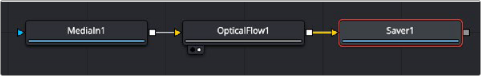
An Optical Flow node rendered out through a Saver node.
Inspector
![]()
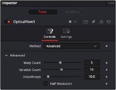
Optical Flow advanced controls
Controls Tab (Advanced)
When you add an Optical Flow, Repair Frame, or Tween node to a Comp, a Method drop-down menu in the Inspector allows you to choose between an Advanced GPU-based algorithm or a Classic
CPU-based algorithm. This Advanced method is the same Optical Flow algorithm used in other DaVinci Resolve pages.
Decreasing this slider makes the optical flow computations faster. To understand what this option does, you must understand that the optical flow algorithm progressively warps one image until
it matches with the other image. After some point, convergence is reached, and additional warps become a waste of computational time. You can tweak this value to speed up the computations, but it is good to watch what the optical flow is doing at the same time.
Decreasing this slider makes the computations faster. In particular, just like adjusting the Warp Count, adjusting this option higher will eventually yield diminishing returns and not produce significantly better results. By default, this value is set to something that should converge for all possible shots and can be tweaked lower fairly often without reducing the disparity’s quality.
This controls the smoothness of the optical flow. Higher smoothness helps deal with noise, while lower smoothness brings out more detail.
The Half Resolution checkbox is used purely to speed up the calculation of the optical flow. The input images are resized down and tracked to produce the optical flow.
Controls Tab (Classic)
By choosing Classic from the Method drop-down menu in the Inspector, you can use the older CPU- based algorithm to maintain compatibility with Comps created in previous versions. This method may also be better suited for some Stereo3D processing.
When using the Classic method, a single slider at the top of the Inspector improves performance by generating proxies. The remaining Advanced section parameters tune the Optical Flow vector
calculations. The default settings serve as a good standard. In most cases, tweaking of the advanced settings is not needed. Many deliver small or diminishing returns. However, depending on the settings, rendering time can easily vary by 10x. If you’re interested in reducing process time, it is best to start by experimenting with the Proxy, Number of Iterations, and Number of Warps sliders and changing the filtering to Bilinear.
![]()
The Proxy slider is used purely to speed up the calculation of the optical flow. The input images are resized down by the proxy scale and tracked to produce the optical flow. The computational time is roughly proportional to the number of pixels in the image. This means a proxy scale of 2 will give a 4x speedup, and a proxy scale of 3 will give a 9x speedup.
This controls the smoothness of the optical flow. Higher smoothness helps deal with noise, while lower smoothness brings out more detail.
This slider is another control for smoothness but applies it based on the color channel. It tends to have the effect of determining how edges in the flow follow edges in the color images. When it is set to a low value, the optical flow becomes smoother and tends to overshoot edges. When it is set to a high value, details from the color images start to slip into the optical flow, which is not desirable. Edges in the flow end up more tightly aligning with the edges in the color images. This can result in streaked- out edges when the optical flow is used for interpolation. As a rough guideline, if you are using the disparity to produce a Z-channel for post effects like Depth of Field, then set it lower in value. If you are using the disparity to perform interpolation, you might want it to be higher in value.
This control sets a threshold for how neighboring groups of foreground/background pixels are matched over several frames. When set to a low value, large structural color features are matched. When set to higher values, small sharp variations in the color are matched. Typically, a good value for this slider is in the [0.7, 0.9] range. When dealing with stereo 3D, setting this option higher tends to improve the matching results in the presence of differences due to smoothly varying shadows or local lighting variations between the left and right images. The user should still perform a color match or deflickering on the initial images, if necessary, so they are as similar as possible. This option also helps with local variations like lighting differences due to light passing through a mirror rig.
This option controls how the penalty for mismatched regions grows as they become more dissimilar. The slider provides a choice between a balance of Quadratic and Linear penalties. Quadratic strongly penalizes large dissimilarities, while Linear is more robust to dissimilar matches. Moving this slider toward Quadratic tends to give a disparity with more small random variations in it, while Linear produces smoother, more visually pleasing results.
Decreasing this slider makes the optical flow computations faster. In particular, the computational time depends linearly upon this option. To understand what this option does, you must understand that the optical flow algorithm progressively warps one image until it matches with the other image. After some point, convergence is reached, and additional warps become a waste of computational time. The default value in Fusion is set high enough that convergence should always be reached. You can tweak this value to speed up the computations, but it is good to watch what the optical flow is doing at the same time.
![]()
Decreasing this slider makes the computations faster. In particular, the computational time depends linearly upon this option. Just like adjusting the Warp Count, adjusting this option higher will eventually yield diminishing returns and not produce significantly better results. By default, this value is set to something that should converge for all possible shots and can be tweaked lower fairly often without reducing the disparity’s quality.
This option controls filtering operations used during flow generation. Catmull-Rom filtering will produce better results, but at the same time, turning on Catmull-Rom will increase the computation time steeply.
Common Controls
The Settings tab in the Inspector is also duplicated in other Optical Flow nodes. These common controls are described in detail at the end of this chapter in “The Common Controls” section.