< Previous | Contents | Next >
The Repair Frame node
Repair Frame Node Introduction
Repair Frame replaces damaged or missing frames or portions of frames with scratches or other temporally transient artifacts. It requires three frames: the repair frame and two neighboring frames. An Optical Flow node is not required for generating motion vectors since the Repair Frame node computes the optical flow. However, this can make it slow to process.
Repair Frame will not pass through, but rather destroys, any aux channels after the computation is done.

TIP: If your footage varies in color from frame to frame, sometimes the repair can be noticeable because, to fill in the hole, Repair Frame must pull color values from adjacent frames. Consider using deflickering, color correction, or using a soft-edged mask to help reduce these kinds of artifacts.
TIP: If your footage varies in color from frame to frame, sometimes the repair can be noticeable because, to fill in the hole, Repair Frame must pull color values from adjacent frames. Consider using deflickering, color correction, or using a soft-edged mask to help reduce these kinds of artifacts.
TIP: If your footage varies in color from frame to frame, sometimes the repair can be noticeable because, to fill in the hole, Repair Frame must pull color values from adjacent frames. Consider using deflickering, color correction, or using a soft-edged mask to help reduce these kinds of artifacts.
See the Optical Flow node for controls and settings information.
![]()
Inputs
There are two inputs on the Repair Frame node. One is used to connect a 2D image that will be repaired and the other is for an effect mask.
— Input: The orange input is used for the primary 2D image that will be repaired.
— Effect Mask: The blue input is for a mask shape created by polylines, basic primitive shapes, paint strokes, or bitmaps from other tools. Connecting a mask to this input limits the repairs to certain areas.
Basic Node Setup
The Repair Frame node analyzes the incoming MediaIn node and repairs single frame issues like dust or scratches.
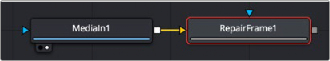
A Repair Frame node set up to analyze a MediaIn node using internal optical flow analysis.
Inspector
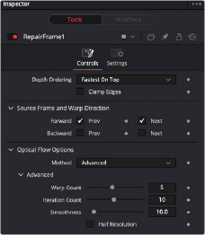
The Repair Frame Controls tab
Controls Tab
The Controls tab includes options for how to repair the frames. It also includes controls for adjusting the optical flow analysis, identical to those controls in the Optical Flow node.
The Depth Ordering determines which parts of the image should be rendered on top by selecting either Fastest On Top or Slowest On Top. The examples below best explain these options.
In a locked-off camera shot where a car is moving through the frame, the background does not move, so it produces small, or slow, vectors, while the car produces larger, or faster, vectors.
![]()
The depth ordering in this case is Fastest On Top since the car draws over the background.
In a shot where the camera pans to follow the car, the background has faster vectors, and the car has slower vectors, so the Depth Ordering method is Slowest On Top.
Under certain circumstances, this option can remove the transparent gaps that may appear on the edges of interpolated frames. Clamp Edges causes a stretching artifact near the edges of the frame that is especially visible with objects moving through it or when the camera is moving.
Because of these artifacts, it is a good idea to use clamp edges only to correct small gaps around the edges of an interpolated frame.
This slider is displayed only when Clamp Edges is enabled. The slider helps to reduce the stretchy artifacts that might be introduced by Clamp Edges.
If you have more than one of the Source Frame and Warp Direction checkboxes turned on, this can lead to doubling up of the stretching effect near the edges. In this case, you’ll want to keep the softness rather small at around 0.01. If you have only one checkbox enabled, you can use a larger softness at around 0.03.