< Previous | Contents | Next >
Region Tab
The Region tab controls the shape, size, and location of the area that emits the particle cells. This is often called the Emitter. Only one emitter region can be set for a single pEmitter node. If the pRender is set to 2D, then the emitter region will produce particles along a flat plane in Z Space. 3D emitter regions possess depth and can produce particles inside a user-defined, three-dimensional region.
For more detail on the Region tab, see “The Common Controls” section at the end of this chapter.
Common Controls
![]()
The Conditions, Style, Region, and Settings tabs are common to all Particle nodes, so their descriptions can be found in “The Common Controls” section at the end of this chapter.
pFlock [pFl]
The pFlock node
pFlock Node Introduction
The pFlock node can be used to simulate the behavior of organic systems, such as a flock of birds or a colony of ants. Its use can make an otherwise mindless particle system appear to be motivated, or acting under the direction of intelligence.
The pFlock node works through two basic principles. Each particle attempts to stay close to other particles and each particle attempts to maintain a minimum distance from other particles.
The strength of these “desires” produces the seemingly motivated behavior perceived by the viewer.
Inputs
The pFlock node has a single orange input by default. Like most particle nodes, this orange input accepts only other particle nodes. A green or magenta bitmap or mesh input appears on the node when you set the Region menu in the Region tab to either Bitmap or Mesh.
— Input: The orange background input takes the output of other particle nodes.
— Region: The green or magenta region input takes a 2D image or a 3D mesh depending on whether you set the Region menu to Bitmap or Mesh. The color of the input is determined by whichever is selected first in the menu. The 3D mesh or a selectable channel from the bitmap defines the area where the flocking takes effect.
Basic Node Setup
When combined with pFollow, the pFlock node can produce natural swarming behaviors that change direction.
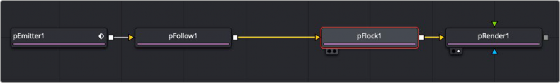
A pFlock node applying more herd-type mentality to particles
![]()
Inspector
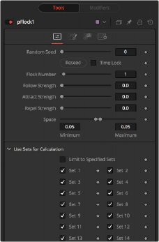
The pFlock controls
The Random Seed slider and Randomize button are presented whenever a Fusion node relies on a random result. Two nodes with the same seed values will produce the same random results. Click the Randomize button to randomly select a new seed value, or adjust the slider to manually select a new seed value.
The value of this control represents the number of other particles that the affected particle will attempt to follow. The higher the value, the more visible “clumping” will appear in the particle system and the larger the groups of particles will appear.
This value represents the strength of each particle’s desire to follow other particles. Higher values will cause the particle to appear to expend more energy and effort to follow other particles. Lower values increase the likelihood that a given particle will break away from the pack.
This value represents the strength of attraction between particles. When a particle moves farther from other particles than the Maximum Space defined in the pFlock node, it will attempt to move closer to other particles. Higher values cause the particle to maintain its spacing energetically, resolving conflicts in spacing more rapidly.
This value represents the force applied to particles that get closer together than the distance defined by the Minimum Space control of the pFlock node. Higher values will cause particles to move away from neighboring particles more rapidly, shooting away from the pack.
![]()
This range control represents the distance each particle attempts to maintain between it and other particles. Particles will attempt to get no closer or farther than the space defined by the Minimum/ Maximum values of this range control. Smaller ranges will give the appearance of more organized motion. Larger ranges will be perceived as disorganized and chaotic.
Common Controls
The Conditions, Style, Region, and Settings tabs are common to all Particle nodes, so their descriptions can be found in “The Common Controls” section at the end of this chapter.