< Previous | Contents | Next >
Gradient Force has only one specific control, which affects the strength of the force and acceleration applied to the particles. Negative values on this control will cause the Gradient Force to be applied from black to white (low values to high values).
Common Controls
The Conditions, Style, Region, and Settings tabs are common to all Particle nodes, so their descriptions can be found in “The Common Controls” section at the end of this chapter.
pImage Emitter [pIE]
The pImage Emitter node
pImage Emitter Node Introduction
![]()
The pImage Emitter node takes an input image and treats each pixel of the image as if it were a particle. The main differences between the pImage Emitter and the normal pEmitter is that instead of emitting particles randomly within a given region, this node emits pixels in a regular 2D grid with colors based on the input image.
Inputs
The pImage Emitter node has three inputs. Like most particle nodes, the orange input accepts only other particle nodes. Green and magenta inputs are 2D image inputs for custom image calculations. Optionally, there are teal or white bitmap or mesh inputs, which appear on the node when you set the Region menu in the Region tab to either Bitmap or Mesh.
— Input: Unlike most other particle nodes, the orange input on the pImage Emitter accepts a 2D image used as the emitter of the particles. If a region is defined for the emitter, this input is used to define the color of the particles.
— Style Bitmap Input: This image input accepts a 2D image to use as the particles’ image. Since this image duplicates into potentially thousands of particles, it is best to keep these images small and square—for instance, 256 x 256 pixels.
— Region: The teal or white region input takes a 2D image or a 3D mesh depending on whether you set the Region menu to Bitmap or Mesh. The color of the input is determined by whichever is selected first in the menu. The 3D mesh or a selectable channel from the bitmap defines the area where the particles are emitted.
Basic Node Setup
The pImage Emitter node is placed at the start of a particle branch, replacing the location of a pEmitter node. Below, a MediaIn node is used to emit particles using the colors from the clip.
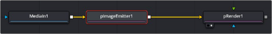
A pImage Emitter node emits particles based on an image connected to the orange input.
![]()
Inspector
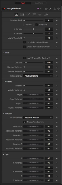
The pImage Emitter controls
The great majority of controls in this node are identical to those found in the pEmitter, and those controls are documented in that previous section. Below are the descriptions of the controls unique to the pImage Emitter node.
The X and Y Density sliders are used to set the mapping of particles to pixels for each axis. They control the density of the sampling grid. A value of 1.0 for either slider indicates 1 sample per pixel. Smaller values will produce a looser, more pointillistic distribution of particles, while values above 1.0 will create multiple particles per pixel in the image.
The Alpha Threshold is used for limiting particle generation so that pixels with semitransparent alpha values will not produce particles. This can be used to harden the edges of an otherwise soft alpha channel. The higher the threshold value, the more opaque a pixel must be before it will generate a particle. Note that the default threshold of 0.0 will create particles for every pixel, regardless of alpha, although many may be transparent and invisible.
Select this checkbox to force the particles to keep the color with which they were born throughout the life of the particle. If this is off, and the input image changes on successive frames, the particles will also change color to match the image. This allows video playback on a grid of particles.
![]()
Enabling this creates a whole new set of particles every frame, instead of just one set on the frame. This can lead to very large particle systems but allows some interesting effects—for example, if the particles are given some initial velocity or if emitting from an animated source. Try a small velocity, an Angle Z of -90, and a seething Fast Noise as a source to get smoothly varying clouds of particles that you could fly through. Note that if this checkbox is left off, only one set of particles is ever created, and thus animating any of the emitter’s other controls will have no effect.
These controls allow you to position the grid of emitted particles.
If the input image used to generate the particles has a Z depth channel, that channel can be used to determine the initial position of the particle in Z space. This can have an interesting hollow shell effect when used in conjunction with camera rotation in the pRender node.
Sets Tab
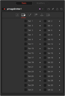
The pImage Emitter Sets tab

NOTE: Pixels with a black (transparent) alpha channel will still generate invisible particles, unless you raise the Alpha Threshold above 0.0. This can slow down rendering significantly.
An Alpha Threshold value of 1/255 = 0.004 is good for eliminating all fully transparent pixels.
The pixels are emitted in a fixed-size 2D grid on the XY plane, centered on the Pivot position. Changing the Region from the default of All allows you to restrict particle creation to more limited areas. If you need to change the size of this grid, use a Transform 3D node after the pRender.
Remember that the various emitter controls apply only to particles when they are emitted. That is, they set the initial state of the particle and do not affect it for the rest of its lifespan. Since pImageEmitter (by default) emits particles only on the first frame, animating these controls will have no effect. However, if the Create Particles Every Frame checkbox is turned on, new particles will be emitted each frame and will use the specified initial settings for that frame.
![]()
Common Controls
The Conditions, Style, Region, and Settings tabs are common to all Particle nodes, so their descriptions can be found in “The Common Controls” section at the end of this chapter.