
< Previous | Contents | Next >
from an image. The RGBA sliders or number fields can be used to enter each color channel’s value or the strength of the alpha channel.
When this checkbox is enabled, the alpha channel value is maintained even when passing through other nodes downstream that may cause the shape to overlap with copies of itself. When disabled, the alpha channel value may increase when the shape overlaps itself.
For instance, if an ellipse’s alpha channel is set to .5, enabling the Allow Combining checkbox maintains that value even if the shape passes through a Duplicate or Grid node that causes the shape to overlap. Disabling the checkbox causes the alpha channel values to be compounded at each overlapping area.
Allow Combining Enabled (left), Allow Combining Disabled (right)
Common Controls
The Settings tab in the Inspector is common to all Shape nodes. These common controls are described in detail at the end of this chapter in “The Common Controls” section.
![]()
sExpand
The sExpand node
The sExpand node is used to dilate or erode shapes. Like almost all Shape nodes, you can only view the sExpand node’s results through a sRender node.
External Inputs
The following input appears on the node’s tile in the Node Editor.
— Input1: [orange, required] This input accepts the output of another shape node. This shape or compound shape connected to this input is either eroded or dilated.
Basic Node Setup
The sExpand node takes a single input that is most often from a compound shape. However, it can be used on single shapes like sStars and sNgons. The output of the sExpand can then be output to another shape node or to a sRender node for viewing or compositing into the greater node tree.
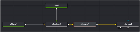
Star and ellipse shapes combined in an sBoolean node, then output to an sExpand for dilating or eroding
Inspector
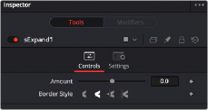
The sExpand Controls tab
Controls
![]()
The Controls tab includes all of the parameters for the sExpand node.
A positive value dilates the shape while a negative value erodes it.
The border style controls how the expanded or contracted shapes join at the corners. There are four styles provided as options. Bevel squares off the corners. Round creates rounded corners. Miter
and Miter Clip maintain pointed edges, until a certain threshold. The Threshold is set by the Miter limit slider.
The Miter parameter is only displayed when the Miter or Miter Clip border style is selected. The miter limit determines when the pointed edges become beveled based on the shape’s thickness.
Common Controls
The Settings tab in the Inspector is common to all Shape nodes. These common controls are described in detail at the end of this chapter in “The Common Controls” section.