< Previous | Contents | Next >
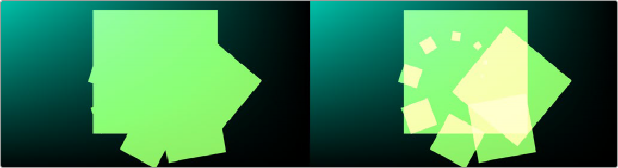
When this checkbox is enabled, the alpha channel value is maintained even when passing through other nodes downstream that may cause the shape to overlap with copies of itself. When disabled, the alpha channel value may increase when the shape overlaps itself. For instance, if a rectangle alpha channel is set to .5, enabling the Allow Combining checkbox maintains that value even if the shape passes through a duplicate or grid node that causes the shape and alpha channel to overlap. Disabling the checkbox causes the alpha channel values to be compounded at each overlapping area.
Allow Combining Enabled (left), Allow Combining Disabled (right)
Common Controls
The Settings tab in the Inspector is common to all Shape nodes. These common controls are described in detail at the end of this chapter in “The Common Controls” section.
![]()
sRender
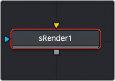
The sRender node
The sRender node converts the vector shapes to an image. The output of the sRender allows the vector shapes to be integrated with other elements in a composite.
Inputs
There is one input on the Background node for an Effect Mask input.
— Input1: [orange, required] This input accepts the output of your final shape node. A rendered bitmap image is created from the sRender node for composting into the rest of your comp.
— Effect Mask: The optional blue effect mask input accepts a mask shape created by polylines, basic primitive shapes, paint strokes, or bitmaps from other tools. Connecting a mask to this input limits the displayed area to only those pixels within the mask.
Basic Node Setup
The sRender node is always placed at the end of a string of Shape nodes. The output connects to other 2D nodes like a Soft Glow node.
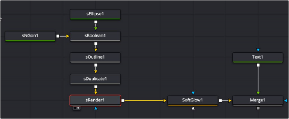
Multiple Shape nodes connected to the sRender node and then processed and composited with a title
Inspector
![]()
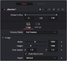
The sRender Image tab
Image Tab
The controls in this tab are used to set the resolution, color depth, and pixel aspect of the image produced by the sRender node.
Use this menu control to select the Fields Processing mode used by Fusion to render the resulting image. The default Full Frames option is appropriate for progressive formats.
This pair of controls are used to set the Width and Height dimensions of the image to be created by the sRender node.
NOTE: Right-click on the Width, Height, or Pixel Aspect controls to display a menu listing the file formats defined in the preferences Frame Format tab. Selecting any of the listed options will set the width, height, and pixel aspect to the values for that format, accordingly.
NOTE: Right-click on the Width, Height, or Pixel Aspect controls to display a menu listing the file formats defined in the preferences Frame Format tab. Selecting any of the listed options will set the width, height, and pixel aspect to the values for that format, accordingly.
NOTE: Right-click on the Width, Height, or Pixel Aspect controls to display a menu listing the file formats defined in the preferences Frame Format tab. Selecting any of the listed options will set the width, height, and pixel aspect to the values for that format, accordingly.
This control is used to specify the Pixel Aspect ratio of the created images. An aspect ratio of 1:1 would generate a square pixel with the same dimensions on either side (like a computer display monitor), and an aspect of 0.9:1 would create a slightly rectangular pixel (like an NTSC monitor).
When this checkbox is selected, the width, height, and pixel aspect of the image created by the node will be locked to values defined in the composition’s Frame Format preferences. If the Frame Format preferences change, the resolution of the image produced by the node will change to match. Disabling this option can be useful to build a composition at a different resolution than the eventual target resolution for the final render.
The Depth button array is used to set the pixel color depth of the image created by the Creator node. 32-bit pixels require 4X the memory of 8-bit pixels but have far greater color accuracy. Float pixels allow high dynamic range values outside the normal 0..1 range, for representing colors that are brighter than white or darker than black.
![]()
You can use the Source Color Space menu to set the Color Space of the footage to help achieve a linear workflow. Unlike the Gamut tool, this doesn‘t perform any actual color space conversion, but rather adds the source space data into the metadata, if that metadata doesn‘t exist. The metadata can then be used downstream by a Gamut tool with the From Image option, or in a Saver, if explicit output spaces are defined there. There are two options to choose from:
— Auto: Automatically reads and passes on the metadata that may be in the image.
— Space: Displays a Color Space Type menu where you can choose the correct color space of the image.
Using the Curve Type menu, you can set the Gamma Space of the footage and choose to remove it by way of the Remove Curve check box when working in a linear workflow. There are three choices in the Curve Type menu
— Auto: Automatically reads and passes on the metadata that may be in the image.
— Space: Displays a Gamma Space Type menu where you can choose the correct gamma curve of the image.
— Log: Brings up the Log/Lin settings, similar to the Cineon tool. For more information,
see Chapter 98, "Film Nodes." in the DaVinci Resolve Reference Manual, or Chapter 37 in the Fusion Reference Manual.