< Previous | Contents | Next >
The Camera Tracker Solve tab
![]()
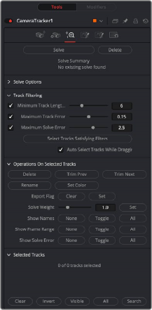
The Solve tab is where the tracking data is used to reconstruct the camera’s motion path along with the point cloud. It is also where cleanup of bad or false tracks is done, and other operations on the tracks can be performed, such as defining which marks are exported in the Point Cloud 3D. The markers can also have their weight set to affect the solve calculations.
For example, a good camera solve may have already been generated, but there are not enough locators in the point cloud in an area where an object needs to be placed, so adding more tracks and setting their Solve Weight to zero will not affect the solved camera but will give more points in the point cloud.
Pressing Solve will launch the solver, which uses the tracking information and the camera specifications to generate a virtual camera path and point cloud, approximating the motion of the physical camera in the live-action footage. The console will automatically open, displaying the progress of the solver.
Delete will remove any solved information, such as the camera and the point cloud, but will keep all the tracking data.
Once the camera has been solved, a summary of the solve calculation is displayed at the top of the Inspector. Chief among those details is the Average Solve Error. This number is a good indicator of whether the camera solve was successful. It can be thought of as the difference (measured in pixels) between tracks in the 2D image and the reconstructed 3D locators reprojected back onto the image through the reconstructed camera. Ultimately, in trying to achieve a low solve error, any value less than
1.0 pixels will generally result in a good track. A value between 0.6 and 0.8 pixels is considered excellent.
Clicking this button selects tracks based on the Track Filtering options. If the Auto Delete Tracks By Filter checkbox is activated, the selected tracks will be deleted as well.
Clicking this button makes a selection of the tracks on fast-moving objects that would otherwise cause a high solve error. The selection is determined by the Foreground Threshold slider.
This slider sets the detection threshold for finding the tracks on fast-moving objects. The higher the value, the more forgiving.
With this checkbox enabled, tracks that are selected by the Clean Tracks By Filter button will be deleted. Enable the checkbox, and then press Clean Tracks By Filter. Any track that meets the filtering options is then selected and deleted.
![]()
With this checkbox enabled, tracks that are selected by the Clean Foreground Tracks button will be deleted. Enable the checkbox, and then press Clean Foreground Tracks. Any track that meets the foreground threshold criteria is deleted.
This slider sets an acceptable maximum threshold level for the solve error. If the solve error is greater than this value, the Camera Tracker will sweep the focal length setting in an attempt to bring the solve error under the Accept Solve Error value. If the solver cannot find a solution, the Camera Tracker
will display a message in the console that the solver failed. If a solution cannot be found, ideally you should try to input the correct focal length or alternatively manually clean some noisy tracks then re-solve.
With this enabled, the Camera Tracker nominates two frames that will be used as a reference for initiating the solve. These two frames are initially solved for and a camera is reconstructed, and then gradually more frames are added in, and the solution is “grown” outward from the seed frames.
The choice of seed frames strongly affects the entire solve and can easily cause the solve to fail. Seed frames can be found automatically or defined manually.
Disabling this will allow the user to select their own two frames. Manual choice of seed frames is an option for advanced users. When choosing seed frames, it is important to satisfy two conflicting desires: the seed frames should have lots of tracks in common yet be far apart in perspective (i.e., the baseline distance between the two associated cameras is long).
Enabling this will allow the solver to adjust the focal length of the lens to match the tracking points. You can prevent the focal length being adjusted by setting the Focal Length parameter in the Camera Tab.
When enabled, lens distortion parameters are exposed to help in correcting lens distortion when solving.
— Refine Center Point: Normally disabled, camera lenses are normally centered in the middle of the film gate but this may differ on some cameras For example, a cine camera may be set up for Academy 1.85, which has a sound stripe on the left, and shooting super35, the lens is offset to the right.

NOTE: When solving for the camera’s motion path, a simulated lens is internally created to model lens distortion in the source footage. This simulated lens model is much simpler than real-world lenses but captures the lens distortion characteristics important for getting an accurate camera solve. Two types of distortion are modeled by Camera Tracker:
Radial Distortion: The strength of this type of distortion varies depending on the distance from the center of the lens. Examples of this include pincushion, barrel, and mustache distortion. Larger values correspond to larger lens curvatures. Modeling radial distortion is especially important for wide angle lenses and fisheye lenses (which will have a lot of distortion because they capture 180 degrees of an environment and then optically squeeze it onto a flat rectangular sensor).
Tangential Distortion: This kind of distortion is produced when the camera’s imaging sensor and physical lens are not parallel to each other. It tends to produce skew distortions in the footage similar to distortions that can be produced by dragging the corners of a corner pin within Fusion. This kind of distortion occurs in very cheap consumer cameras and is practically non-existent in film cameras, DSLRs, and pretty much any kind of camera used in film or broadcast. It is recommended that it be left disabled.
— Refine Lens Parameters: This will refine the lens distortion or curvature of the lens. There tends to be larger distortion on wide angle cameras
![]()
When disabled, the Camera Tracker does not do any lens curvature simulations. This is the default setting and should remain disabled if there is a very low distortion lens or the lens distortion has already been removed from the source clip. Activating the Enable Lens Parameters checkbox determines which lens parameters will be modeled and solved for. Parameters that are not enabled will be left at their default values. The following options are available:
— Radial Quadratic: Model only Quadratic radial lens curvature, which is either barrel or pincushion distortion. This is the most common type of distortion. Selecting this option causes the low and high order distortion values to be solved for.
— Radial Quartic: Model only Quartic radial lens curvature, which combines barrel and pincushion distortion. This causes the low and high order distortion values to be solved for.