< Previous | Contents | Next >
The Spherical Camera node
Spherical Camera Node Introduction
The Spherical Camera is not located in the VR category of the Effects Library but in the 3D category. However, it is commonly used in creating and fixing VR content, so it is referenced here. The Spherical Camera allows the 3D Renderer node to output an image covering all viewing angles, laid out in several different formats. This image may be used, for example, as a skybox texture or reflection map or viewed in a VR headset. The Image Width setting in the 3D Renderer sets the size of each square cube face so that the resulting image may be a multiple of this size horizontally and vertically.
For more detail on the Spherical Camera node, refer to Chapter 29, “3D Nodes,” in the Fusion Reference Manual or see Chapter 89, "3D Nodes," in the DaVinci Resolve Reference Manual.
Spherical Stabilizer

NOTE: The VR category and Spherical Stabilizer node are available only in Fusion Studio and DaVinci Resolve Studio.
NOTE: The VR category and Spherical Stabilizer node are available only in Fusion Studio and DaVinci Resolve Studio.
NOTE: The VR category and Spherical Stabilizer node are available only in Fusion Studio and DaVinci Resolve Studio.
![]()
The Spherical Stabilizer node
Spherical Stabilizer Node Introduction
VR live action often uses handheld cameras, causing shaky footage to be a common problem. The Spherical Stabilizer node automatically identifies and tracks visible features in the footage, and then analyzes their movement to identify pan, tilt, and roll rotations. After tracking, it is then possible to smooth out or stabilize the rotation of the footage.
Inputs
The Spherical Stabilizer node has a single orange input.
— Image: This orange image input node requires an image in a spherical layout, which can be any of Lat Long (2:1 equirectangular), Horizontal/Vertical Cross, or Horizontal/Vertical Strip.
Basic Node Setup
In the example below, a 2:1 Lat Long image is connected to the input of the Spherical Stabilizer node. Once the image is stabilized, the output of the Spherical Stabilizer node is a steadied clip.
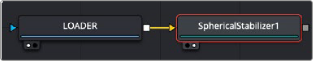
Spherical Stabilizer set up to steady a 2:1 Lat Long clip
Inspector
![]()
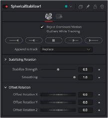
The Spherical Stabilizer Controls tab
Controls Tab
The Controls tab contains parameters to initiate the tracking and modify the results for stabilization or smoothing.
With this control activated (the default setting), features that move contrary to the majority of other features are ignored. This helps ignore the movement of subjects in the shot, preferring stable and consistent markers from the surrounding environment.
These buttons initiate tracking and analysis of the shot. Be aware that the reference frame used for stabilization is set to the first frame tracked.
— Track Backward from End Frame starts tracking backward from the end of the current render range.
— Track Backward from Current Time starts tracking backward from the current frame.
— Stop ceases tracking, preserving all results so far.
— Track Forward from Current Time starts tracking forward from the start of the current render range.
— Track Forward from Start Frame starts tracking forward from the current time.
— Replace causes the Track Controls to discard any previous tracking results and replace them with the newly-created track.
— Append adds the new tracking results to any earlier tracks.
This control varies the amount of smoothing or stabilization applied, from 0.0 (no change) to
1.0 (maximum).
The Spherical Stabilizer node can eliminate all rotation from a shot, fixing the forward viewpoint (Still mode, 0.0) or gently smooth out any panning, rolling, or tilting to increase viewer comfort (Smooth mode, 1.0). This slider allows either option or anything in between.
![]()
Often a shot is not entirely level and needs the horizon to be realigned, or perhaps a desired pan should be reintroduced after fully stabilizing the shot. The Offset Rotation controls allow additional manual control of the Spherical Stabilizer’s rotation of the footage, for pitch/tilt (X), pan/yaw (Y), and roll (Z), respectively. Rotation is always performed in the order X, Y, Z.
Common Controls
The Settings tab in the Inspector is duplicated in other VR nodes. These common controls are described in detail in the following “The Common Controls” section.