< Previous | Contents | Next >
Offset (Angle, Distance, Position)
There are three Offset modifiers used to create variances between values. Depending on the modifier, these values relate to controls, paths, and points. The three types of Offset modifiers available in Fusion are:
— Offset Angle
— Offset Distance
— Offset Position
![]()
The Offset Angle modifier outputs a value between 0 and 360 that is based on the angle between two positional controls. The Position and Offset parameters may be static, connected to other positional parameters, or connected to paths of their own. All offsets use the same set of controls, which behave differently depending on the offset type used. These controls are described below.
The Offset Distance modifier outputs a value that is based on the distance between two positional controls. This modifier is capable of outputting a value based on a mathematical expression applied to a position.
The Offset Position modifier generates a position (X and Y coordinates) that is based on the relationship between positional controls. This modifier is the equivalent of a calculation control except that it outputs X and Y coordinates instead of a value.
It can be applied by right-clicking a control and selecting Modify With > Offset.
Inspector
The Offset Position modifier controls
Offset Tab
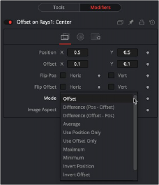
The Inspector for all three Offset modifiers is identical. The Offset tab includes Position and Offset values as well as a Mode menu for selecting the mathematical operation performed by the offset control.
The X and Y values are used by the Position to generate the calculation.
![]()
The X and Y values are used by the Offset to generate the calculation.
When these controls are selected, the Position is mirrored along the vertical or horizontal axis of the image.
When these controls are selected, the Offset position is mirrored along the vertical or horizontal axis of the image.
The Mode menu includes mathematical operations performed by the Offset control. Available options include:
— Offset
— Difference (Position - Offset)
— Difference (Offset - Position)
— Average
— Use Position Only
— Use Offset Only
— Maximum
— Minimum
— Invert Position
— Invert Offset
— Invert Sugar
— Random Offset
Adjust the modifier’s output to compensate for the image aspect (not pixel aspect) of the project. A square image of 500 x 500 would use an Image Aspect value of 1, and a rectangular image of 500 x 1000 would use an Aspect Value of 2. The default value is always based on the current frame format selected in the preferences. To calculate image aspect, divide the width by the height. This control can also be used to create the illusion of aspect.
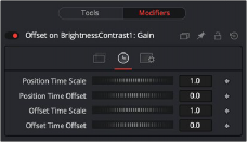
The Offset Time tab
Time Tab
This returns the value of the Position at the Time Scale specified (for example, 0.5 is the value at half the current frame time).
This returns the value of the Position at the Time Offset specified (for example, 10 is 10 frames back).
This returns the value of the Offset at the Time Scale specified.
![]()

EXAMPLE
This is a simple comp to illustrate one potential use of offsets.
1. Create a new Comp 100 frames long.
2. Create a node tree consisting of a black background and a Text node foreground connected to a Merge.
3. In the Text Layout tab, use the Center X control to animate the text from the left side of the screen to the right.
4. Move to frame 0.
5. In the Text tab in the Inspector, right-click the Size control and select Modify With > Offset Distance from the contextual menu.
6. This adds two onscreen controls: a crosshair for the position and an X control for the offset. These onscreen controls represent the Position and Offset controls displayed in the Modifiers tab.
The size of the text is now determined by the distance, or offset, between the two onscreen controls.
This returns the value of the Offset at the Time Offset specified.

7. Drag the X onscreen control in the viewer to see how the distance from the crosshair changes the size of the merge and by association the text.
Both the crosshair and the X onscreen controls are animatable and can be connected to other controls.
8. Position the X centered at the bottom of the viewer.
9. In the Inspector, select the Modifiers tab.
10. In the Offset on Text size section, right-click over Position and choose Connect To > PathConnect the position value of the Offset to the existing path by right-clicking the Position control and selecting Connect To > Path1 Position.
11. Play the comp to view the animation.
12. Now, the text shrinks near the center of the path (when the distance between the offset and the path is at its minimum) and grows at its ends (where the distance between the offset and the path is at its maximum).