< Previous | Contents | Next >
The Node Editor’s Pan (Hand) tool
The Components of a Node Tree
Ambitious grades may require trees of multiple nodes to create the necessary effect. This section covers the mechanics of putting nodes together into the structures that are described in more detail later in this chapter.
Every node you add is a “Corrector” node, which is capable of either primary or secondary correction, depending on whether or not you enable the Qualifier/Window/Matte controls. Even “Serial” and “Parallel” nodes are simply Corrector nodes that are added in series or in parallel to the previous node in the node tree; the names are a consequence of how they’re added.
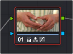
Each Corrector node has two inputs and two outputs, which lets you separately manage the RGB image-processing channel, and the Key channel that defines areas of isolation for image processing operations, or transparency for compositing. RGB connections are light green, located at the top left and right of each node. Key connections are blue, located at the bottom left and right of each node. Inputs into the node are triangles, and outputs are squares. These inputs and outputs let you control the flow of image and isolation channels coming into and going out of each node in the tree.
A single node, the RGB (green) and key (blue) triangular inputs and square outputs are clearly visible
![]()
Nodes are attached to one another via “connections,” seen as lines that connect one node to another. Image data flows from left to right, starting with the Source input all the way at the left of the Node Editor, through each node in the tree, and ending at the Node Tree output at the right of the Node Editor.
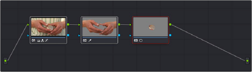
A simple serial arrangement of corrections
Here’s an explanation of the different components of a basic node tree where all nodes are connected in serial, one after the other, and how they work together:
— Source Input: The green source node to the far left is the clip’s image data as processed by the Sizing and Source decode settings, ungraded. The Source input feeds RGB data to the grade, and is connected to the RGB input of the first node in your tree. If necessary, you can connect the Source input to more than one Corrector node, creating multiple simultaneous streams of image processing emerging from the original source state of the image that you can eventually recombine in different ways using the Parallel or Layer Mixer nodes.
— Nodes: Each node in the node graph represents a collection of image processing operations that can be enabled or disabled separately from any other node in the graph. By separating operations into multiple nodes, you’re able to precisely control the order of all image processing operations in DaVinci Resolve to create many different corrections and effects. The green RGB inputs and outputs are used to connect these nodes together. Each node’s thumbnail image shows how the clip looks at that particular stage of the grade, giving you a visual indication of what each node is doing, and small badges below each node show you which specific operations are being applied by that node.
— RGB Inputs and Outputs: The green inputs and outputs at the upper right and left of each node are used to connect the RGB image that’s output from one node to the RGB input of the next node. For a Corrector node to have an effect, you must connect both its RGB input and its RGB output to neighboring nodes in the tree. Furthermore, every single node in the Node Editor must be connected for a grade to be enabled; having any disconnected node in the node tree disables that grade until it’s fully connected.
— Key Inputs and Outputs: The blue inputs and outputs at the bottom right and left of each node are used to route the key channel generated by a node’s Qualifier or Window controls, or imported via a Matte clip that you previously associated with a clip in the Media page. When you
connect the key output of one node to the key input of another, you basically copy the first node’s key to the second node. You can also combine the key outputs of multiple nodes in various ways using the Key Mixer node.
![]()
— Node Tree Output: The RGB output of the last node in a tree must be connected to the green Node Tree output node, which “completes the circuit” of image processing, and passes that correction on to the next stage in the DaVinci Resolve image processing pipeline. If the output is not connected, the node tree is disabled and has no effect on the clip. You can only connect one RGB output at a time to the Node Tree output.
— Second Source Input (for RED HDRx): You can access the alternate highlight exposure of RED HDRx media by exposing this optional second Source input. For more information, see
“Mulit-Channel RED HDRx Support” in Chapter 143, “Channel Splitting and Image Compositing.”
— Second Source Input (from Fusion page): You can also create additional sources to route in masks or mattes created in the Fusion page for use as keys in the Color page.
— Alpha Output: It’s possible to create regions of transparency for compositing directly in DaVinci Resolve by connecting a key output to an optional Alpha output. For more information, see Chapter 143, “Combining Keys and Using Mattes.”