< Previous | Contents | Next >
Fairlight Console Channel Control
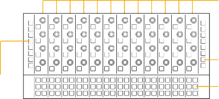
The secret to managing high track counts for large projects is the Fairlight Console Channel Control because it provides instant knob-per-function access to channel parameters along with real-time high resolution visual feedback on-screen. The Fairlight Console Channel Control module fits directly below the LCD monitor so that you can always see the graphical representation of each parameter as it is modified with the adjacent channel controls. There are four types of channel controls organized in three areas of the panel.
On the far left and right sides of the panel, you’ll find dual-function Channel Display buttons that determine the current channel control mode and which parameters are displayed on the LCD monitor.
The middle of the panel contains 12 groups of multi functional Channel Control buttons and knobs that align with the 12 faders on the Channel Fader panel. The knobs are used to adjust parameter values, while the control buttons act as toggles, On/Off, or In/Out switches for active parameters.
The fourth type of controls are the In-Line Channel Extension Buttons, which are arranged in groups of six below each of the 12 channel control groups. Here you’ll find dedicated channel-specific buttons for functions available in the Fairlight page Mixer and Timeline track headers.
Channel Control buttons and knobs for each corresponding fader channel
Channel Display buttons
In-Line Channel Display buttons
In-Line Channel Extension buttons
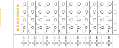
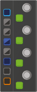
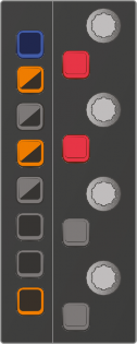
The primary display controls for the channel control components are the dual-function channel display buttons located on the left and right sides of the Channel Control panel. These bi-colored LED buttons determine the channel mode and current parameters displayed on-screen. There are a total of 16 display buttons split evenly into groups of eight buttons on each side of the panel. On the left side of the panel, you’ll find eight channel display buttons used to select the channel control mode
as well as display plugins and automaton parameters; while the display buttons on the right side of the panel are used to show the in-line channel parameters found in the Fairlight page Mixer, such as Pan, EQ, and Dynamics. The top and bottom display buttons are identical on both sides of the panel to provide easy access to the CTL (control) and ALT (alternate) functions for selecting secondary display features, resetting parameters to default values, and showing alternate controls in the LCD.
The default color for all display buttons is yellow, except for the Control button, which is always blue. When the Control button is pressed, inactive display buttons with secondary functions turn blue or purple. Active display buttons remain in their active state color until another display button is selected. For example, if a secondary function is selected, that display button remains purple as long as it is active, while the other display buttons return to yellow when the Control button is released.
Channel Display buttons
Channel Display buttons
Channel Display buttons
![]()
while touching one of the knobs or faders will reset any of the touch-sensitive controls to their default values. For example, holding the Control button while touching a fader or Aux send knob resets the value to 0 dB and is the Fairlight Console Control equivalent to double-clicking the mouse on a fader or knob in the Fairlight page GUI.
There are a total of three conveniently located Control buttons on a Channel Control bay; two on the Channel Control panel, and one on the Channel Fader panel.
![]()
![]()
![]()
If multiple channels are selected, you’ll see parameters for the last track selected or called. In this version of the software, the secondary U3 function is not implemented.
![]()
![]()
![]() SPLL: SPLL is not used in this version of the software.
SPLL: SPLL is not used in this version of the software.
![]()
![]()
![]()
![]()
![]()
![]()
![]()
![]()
![]()
![]()
![]()
![]()
![]()
![]()
|
|
|
|
|
|
|
|
|
|
|
|
| |
| |||||||||||||
|
|
|
|
|
|
|
|
|
|
|
|
| |
| |||||||||||||
|
|
|
|
|
|
|
|
|
|
|
|
| |
| |||||||||||||
![]()
![]()
![]()
![]()
![]()
![]()
![]()
![]()
![]()
![]()
![]()
![]()
![]()
![]()
![]()
![]()
![]()
![]()
![]()
![]()
![]()
![]()
![]()
![]()
![]()
![]()
In-Line Channel Display buttons
![]()
![]()
![]()
the ALT button for Gain control of each of the four bands. Use the Control key for the secondary button function to display and modify the two channel filters for High-pass, Low-pass, High-shelf or Low-shelf filtering. While in EQ/FILT In-Line display mode, the Channel Control touch-sensitive knobs are used to sweep Frequencies or Gain, and the Channel Control buttons toggle between Bell, Notch, High Pass Filter (HPF), Low Pass Filter (LPF), High Shelf (Hi-Sh), and Low Shelf (Lo-Sh) filtering curves. The functionality of EQ/ FILT works the same as using the Channel EQ window available on the Fairlight page Mixer.
![]()
Pressing the Aux key while holding Control will toggle between Aux 9-12 or 13-16. Press the ALT button for the alternate Pre/Post fader controls for the Aux send.
![]()
![]()
and press LIM to access the Makeup gain controls. The secondary U2 function is not implemented in this version of the software.
![]()
Control and press EXP/U3 to access the Makeup gain controls. The secondary U3 feature is not implemented in this version of the software.

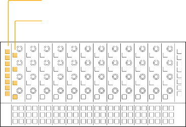
NOTE: Non-functioning Channel Display buttons, such as PLUG and ENAB, remain unlit. These buttons will be operational in future software updates.
NOTE: Non-functioning Channel Display buttons, such as PLUG and ENAB, remain unlit. These buttons will be operational in future software updates.
NOTE: Non-functioning Channel Display buttons, such as PLUG and ENAB, remain unlit. These buttons will be operational in future software updates.
![]()
Channel Display buttons Channel Control buttons
Channel Display buttons Channel Control buttons
Channel Display buttons Channel Control buttons
CTL
CTL
CTL
MSTR
U1
MSTR
U1
MSTR
U1
PLUG
U2
PLUG
U2
PLUG
U2
CHAN
U3
CHAN
U3
CHAN
U3
ENAB
COPY
ENAB
COPY
ENAB
COPY
CURVE
CURVE
CURVE
SPLL
SPLL
SPLL
ALT
ALT
ALT
CTL
CTL
CTL
MSTR
U1
MSTR
U1
MSTR
U1
PLUG
U2
PLUG
U2
PLUG
U2
CHAN
U3
CHAN
U3
CHAN
U3
ENAB
COPY
ENAB
COPY
ENAB
COPY
CURVE
CURVE
CURVE
SPLL
SPLL
SPLL
ALT
ALT
ALT
CTL
CTL
CTL
MSTR
U1
MSTR
U1
MSTR
U1
PLUG
U2
PLUG
U2
PLUG
U2
CHAN
U3
CHAN
U3
CHAN
U3
ENAB
COPY
ENAB
COPY
ENAB
COPY
CURVE
CURVE
CURVE
SPLL
SPLL
SPLL
ALT
ALT
ALT
CTL
CTL
CTL
MSTR
U1
MSTR
U1
MSTR
U1
PLUG
U2
PLUG
U2
PLUG
U2
CHAN
U3
CHAN
U3
CHAN
U3
ENAB
COPY
ENAB
COPY
ENAB
COPY
CURVE
CURVE
CURVE
SPLL
SPLL
SPLL
ALT
ALT
ALT
The left-side Channel Display buttons without modifiers and with Control button pressed to show secondary functions
![]()
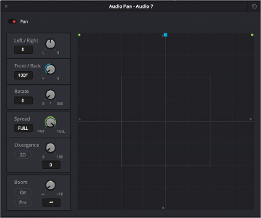
Pan Settings window in the Fairlight page interface, available in the Mixer
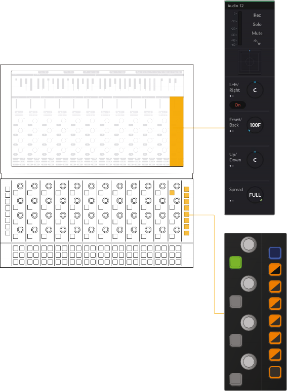
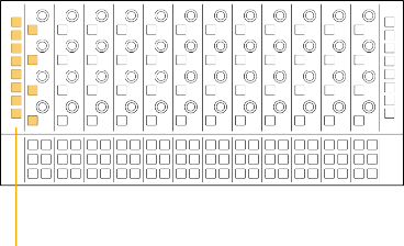
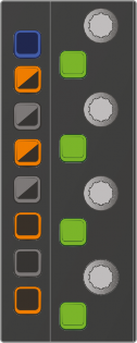
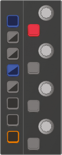
The right-side In-Line Channel Display buttons with Pan/Path button pressed and corresponding Pan controls in the Channel Control LCD
The right-side In-Line Channel Display buttons with Pan/Path button pressed and corresponding Pan controls in the Channel Control LCD
The right-side In-Line Channel Display buttons with Pan/Path button pressed and corresponding Pan controls in the Channel Control LCD
CTL
PAN PATH
EQ
FILT
AUX AUX
COMP
U1
LIM
U2
EXP
U3
ALT
CTL
PAN PATH
EQ
FILT
AUX AUX
COMP
U1
LIM
U2
EXP
U3
ALT
CTL
PAN PATH
EQ
FILT
AUX AUX
COMP
U1
LIM
U2
EXP
U3
ALT
![]()
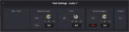
Path Settings window in the Fairlight page interface, available in the Mixer, Input drop-down menu