< Previous | Contents | Next >
— Winding Ray Direction: A 3D model is a mesh of vertices made up of flat polygons. When making this a volume for a region, the Winding Ray Direction is used to determine in which direction the volume of each polygon (like depth extrude) is aligned.
— Limit by Object ID: When a scene with multiple meshes is connected to the green Mesh input on the node, all the meshes are used as the region. Enabling this checkbox allows you to use the Object ID slider to select the ID for the mesh you want to use as the Region.
— Object ID: When the Limit by Object ID checkbox is enabled, this slider selects the number ID for the mesh object you want to use for the Region.
Common Controls
The Settings tab controls are common to many 3D nodes, and their descriptions can be found in “The Common Controls” section at the end of this chapter.
Extrude 3D [3Ex]
The sPolygon node
![]()
Extrude 3D Node Introduction
The Extrude3D tool operates on Fusion’s shape tools, taking flat shapes and transforming them into dynamic, three-dimensional objects through controlled extrusion, pushing the shape’s edges into the Z-axis. Additional beveling can be applied to create polished edges and chamfers.
Inputs
There are three inputs to this node, one for inputing the shape itself, and two for materials.
— ShapeInput: This yellow input expects a Shape node. This is the 2D shape that you want to bevel and extrude into 3D space.
— MaterialInput: The green-colored material input accepts either a 2D image or a 3D material. It provides the texture for the shape based on the connected source, such as a Loader node in
Fusion Studio or a MediaIn node in DaVinci Resolve. The 2D image is used as a diffuse texture map for the Basic Material tab in the Inspector. If a 3D material is connected, then the Basic Material tab is disabled.
— BevelMaterialInput: The pink-colored material input accepts either a 2D image or a 3D material. It provides the texture for the bevel based on the connected source, such as a Loader node in Fusion Studio or a MediaIn node in DaVinci Resolve. The 2D image is used as a diffuse texture map for the Basic Material tab in the Inspector. If a 3D material is connected, then the Basic Material tab is disabled.
Basic Node Setup
The Extrude 3D node is primarily used to create a 3D shape from a 2D shape. The Shape Node node is connected to the Extrude 3D node, and the Extrude 3D node is then connected to a Merge 3D node. Viewing the Merge 3D node will show the Extrude 3D node and other elements connected to it.
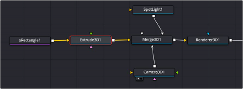
A simple sRectangle Shape node connected to an Extrude 3D node brings the rectangle into 3D space.
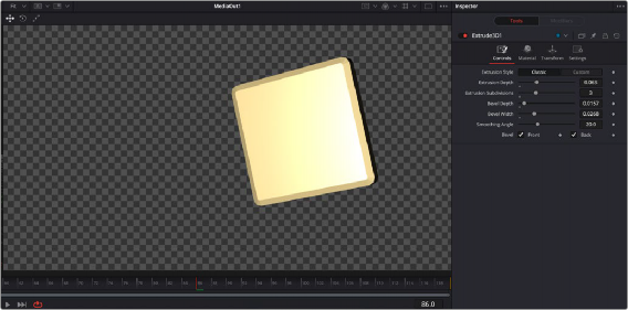
![]()
A simple sRectangle extruded into 3D space and beveled
Inspector
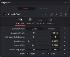
The Extrude3D Controls tab
Controls
The Controls tab is used to define the polygon characteristics, including extrusion depth and beveling.
There are two choices: Classic and Custom. Classic gives a standard uniform extrusion, while Custom exposes an Extrusion Profile graph that lets you add points and manipulate them to create unique custom extrusions, like picture frames and knurled buttons.
This slider determines the extruded width of the polygon.
This slider determines the number of subdivisions within the smoothed portions of the extrusion profile.
Increase the value of the Bevel Depth slider above zero to add a bevel to the polygon.
This slider determines the width of the polygon’s bevel.
Use this control to adjust the smoothing angle applied to the edges of the bevel.
Use these checkboxes to enable beveling for the front and back faces of the polygon separately.
Common Controls
![]()
The Materials tab, Transforms tab, and Settings tab in the Inspector are also duplicated in other 3D nodes. These common controls are described in detail at the end of this chapter in “The Common Controls” section.