< Previous | Contents | Next >
The Alpha mode is used to control how the Catcher combines the Alpha channels from multiple projectors. It has no effect on the results when only one projector is in the scene. This control is designed to work with the software renderer in the Renderer 3D node and has no effect when using the OpenGL renderer.
The Threshold can be used to exclude certain low values from the accumulation calculation.
For example, when using the Median Accumulation mode, a threshold of 0.01 would exclude any pixel with a value of less than 0.01 from the median calculation.
When active, the Catcher only receives light from projectors with a matching ID. Projectors with a different ID are ignored.
This slider sets the numeric identifier assigned to this material. This value is rendered into the MatID auxiliary channel if the corresponding option is enabled in the Renderer 3D node.
Common Controls
The Settings tab in the Inspector is duplicated in other 3D nodes. These common controls are described in detail at the end of this chapter in “The Common Controls” section.
![]()
CubeMap [3Cu]
The Cube Map node
Cube Map Node Overview
The Cube Map node creates texture maps using separate images for each face of the cube. It can also extract the individual faces of the cube from a single image containing an unfolded cube in the Vertical or Horizontal Cross layouts.
A cube map is produced by mounting six cameras at 90 degrees angle of views to point up, down, left, right, front, and back.
The node provides options to set the reference coordinate system and rotation for the resulting texture map. The Cube Map node is typically used to produce environment maps for distant areas (such as skies or horizons) or reflection and refraction maps.
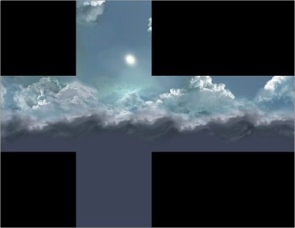
Sample cube map
Inputs
The Inputs on this node change based on the settings of the Layout menu in the Inspector. The single input uses a 2D image for the entire cube, while six inputs can handle a different 2D image for each side of a cube.
— CrossImage: The orange Cross Image input is visible by default or when the Layout menu in the Inspector is set to either Vertical Cross or Horizontal Cross. The input accepts a 2D image.
![]()
— CubeMap.[DIRECTION]: These six multi-colored inputs are visible only when the Layout menu in the Inspector is set to Separate Images. Each input accepts an image aligned to match the left, right, top, bottom, front, and back faces.
Basic Node Setup
The Cube Map node uses a vertical or horizontal cross image represented by MediaIn2 node connected into the orange cross image input. The Cube Map node is used similarly to the Sphere Map node. It creates an environment that surrounds the geometry connected to a Shader node.
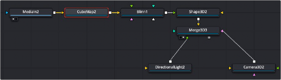
A Cube Map node receives a cross image input, creating an environment for the Shape 3D
Inspector
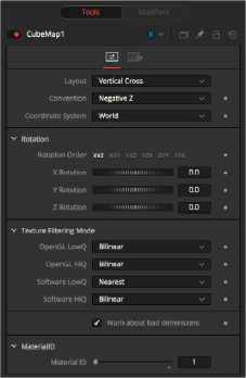
Cube Map controls
Controls Tab
The Layout menu determines the type and number of inputs for the cube map texture. Valid options are:
![]()
— Separate Images: This option exposes six inputs on the node, one for each face of the cube. If the separate images are not square or not of the same size, they are rescaled into the largest 1:1 image that can contain all of them.
— Vertical Cross: This option exposes a single input on the node. The image should be an unwrapped texture of a cube containing all the faces organized into a Vertical Cross formation, where the height is larger than the width. If the image aspect of the cross image is not 3:4, the CubeMap node crops it down so it matches the applicable aspect ratio.
— Horizontal Cross: This option exposes a single input on the node. The image should be an unwrapped texture of a cube containing all the faces organized into a Horizontal Cross formation, where the width is larger than the height. If the image aspect of the cross image is not 4:3, the CubeMap node crops it down so that matches the applicable aspect ratio.
The coordinate system menu sets the position values used when converting the image into a texture.
— Model: This option orients the texture along the object local coordinate system.
— World: This option orients the resulting texture using the global or world coordinate system.
— Eye: This option aligns the texture map to the coordinate system of the camera or viewer.