< Previous | Contents | Next >
The rotation controls are divided into buttons that select the order of rotation along each axis of the texture. For example, XYZ would apply the rotation to the X axis first, followed by the Y axis, and finally the Z axis. The other half of the rotation controls are dials that rotate the texture around its pivot point.
Selecting this checkbox displays a warning message on the console if the dimensions of the image provided did not meet the requirements of the selected orientation mode.
This slider sets the numeric identifier assigned to this material. This value is rendered into the MatID auxiliary channel if the corresponding option is enabled in the renderer.
Common Controls
The Settings tab in the Inspector is duplicated in other 3D nodes. These common controls are described in detail at the end of this chapter in “The Common Controls” section.
Falloff [3Fa]
![]()
The Falloff node
Falloff Node Overview
The Falloff node blends two materials or textures together based on the incidence angle between the object to which the material is applied and the camera. This is useful when you wish to use one material for portions of the geometry that would reflect light directly back to the camera and a different material for parts that reflect light back into the scene.
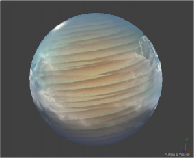
Falloff example
Inputs
The two Inputs on the Falloff node are used to connect two images or materials. One is used to reflect back at the camera, while the other reflects away from the camera and into the scene.
— Face On Material: The orange Face On material input accepts a 2D image or a 3D material. If a 2D image is provided, it is turned into a diffuse texture map using the basic material shader. This input is used for the material that is reflecting directly back to the camera
— Glancing Material: The green Glancing material input accepts a 2D image or a 3D material. If a 2D image is provided, it is turned into a diffuse texture map using the basic material shader. This input is used for the material that is reflecting away from the camera and into the scene.
While the inputs for this node can be images, the output is always a material.
Basic Node Setup
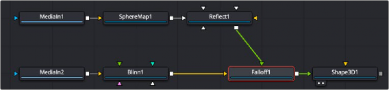
The Falloff node below is used to control the strength of the Blinn material and the Reflect material. You connect the Face On input of the Falloff node to the material you want shown for the sides of the object that face the camera and connect the Glance input to the material you want shown for the sides not directly facing the camera.
![]()
The Falloff node uses one input for the material facing the camera and one for the material not directly facing the camera.
Inspector
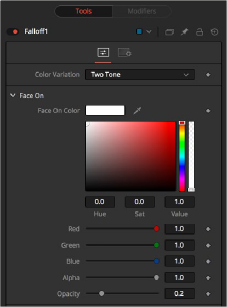
Falloff controls
Controls Tab
The parameters in the Controls tabs modify the tint and opacity of the Face On material and the Glancing material. A Falloff slider controls the blending between the two.
— Two Tone: Two regular Color controls define the colors for Glancing and Face On.
— Gradient: A Gradient control defines the colors for Glancing and Face On. This can be used for a multitude of effects, like creating Toon Shaders, for example.
The Face On Color defines the color of surface parts facing the camera. If the Face On texture map is provided, then the color value provided here is multiplied by the color values in the texture.
Reducing the material’s opacity decreases the color and Alpha values of the Face On material, making the material transparent.
The Glancing Color defines the color of surface parts more perpendicular to the camera. If the Glancing material port has a valid input, then this input is multiplied by this color.
Reducing the material’s opacity decreases the color and Alpha values of the Glancing material, making the material transparent.
This value controls the transition between Glancing and Face On strength. It is very similar to a gamma operation applied to a gradient, blending one value into another.
![]()
This slider sets the numeric identifier assigned to this material. This value is rendered into the MatID auxiliary channel if the corresponding option is enabled in the renderer.
Common Controls
The Settings tab in the Inspector is duplicated in other 3D nodes. These common controls are described in detail at the end of this chapter in “The Common Controls” section.