< Previous | Contents | Next >
(3D only) The Scale Z value scales the noise texture along the W-axis in texture space. W represents a direction perpendicular to the UV plane for a 3D texture map.
(2D only) The Seethe control smoothly varies the 2D noise pattern.
(2D only) As with the Seethe control above, the Seethe Rate also causes the noise map to evolve and change. The Seethe Rate defines the rate at which the noise changes each frame, causing an animated drift in the noise automatically, without the need for spline animation.
Normally, the noise function interpolates between values to create a smooth continuous gradient of results. You can enable the Discontinuous checkbox to create hard discontinuity lines along some of the noise contours. The result is a dramatically different effect.
Enable the Invert checkbox to invert the noise, creating a negative image of the original pattern. This is most effective when Discontinuous is also enabled.
This slider sets the numeric identifier assigned to this material. This value is rendered into the MatID auxiliary channel if the corresponding option is enabled in the renderer.
Common Controls
![]()
The Settings tab in the Inspector is duplicated in other 3D nodes. These common controls are described in detail at the end of this chapter in “The Common Controls” section.
Gradient 3D [3Gd]
The Gradient node
Gradient Node Overview
The Gradient 3D node is used to texture objects with a variety of gradient types. It offers many of the same controls as the Background node. While it is not possible to transform the gradient directly in 3D space, it is orientable using the following nodes:
— Texture Transform Node: The Texture Transform node can be used to adjust the mapping per pixel.
— UV Map Node: The UV Map node can be used to adjust the mapping per vertex (use the
XYZtoUVW mode). This has onscreen controls, so you can see what the gradient is doing. Using this node is recommended because it is faster to evaluate.
The gradient defaults to a linear gradient that goes from -1 to +1 along the Z-axis. All primitives in the Shape 3D node can output a third texture coordinate for UVW mapping.
Inputs
The Gradient node has no Inputs. The output of the node is connected to a material input on 3D geometry.
Basic Node Setup
The Gradient 3D node below is used to generate a resolution-independent 3D texture for an FBX imported model. Positioning in UVW space is easiest to do using a UV Map tool placed after the geometry.
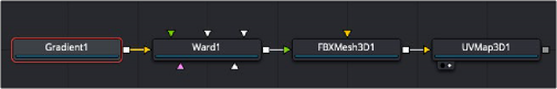
A Gradient 3D node generates a resolution-independent gradient texture positioned by the UV Map tool
![]()
Inspector
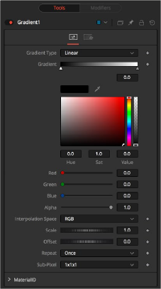
Gradient 3D controls
Controls Tab
The Controls tab for the Gradient node control the pattern and colors used for the gradient texture.
Determines the type or pattern used for the gradient.
— Linear: A simple linear gradient.
— Reflect: Based on the Linear mode, this gradient is mirrored at the middle of the textured range.
— Square: The gradient is applied using a square pattern.
— Cross: Similar to the Reflect mode, but Cross uses two axes to apply the gradient.
— Radial: The Radial mode uses a circular pattern to apply the gradient.
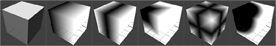
Gradient 3D modes
The Gradient control consists of a bar where it is possible to add, modify, and remove color stops of the gradient. Each triangular color stop on the Gradient bar represents a color in the gradient. It is possible to animate the color as well as the position of the point. Furthermore, a From Image modifier can be applied to the gradient to evaluate it from an image.
![]()
The gradient is linearly interpolated from point to point in RGB color space by default. This can sometimes lead to unwanted colors. Choosing another color space may provide a better result.
Allows sizing of the gradient.
Allows panning through the gradient.
Defines how the left and right borders of the gradient are treated.
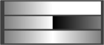
Gradients set to Once, Repeat, and Ping Pong from top to bottom, respectively, and shifting the gradient to the left
— Once: When using the Gradient Offset control to shift the gradient, the border colors keep their values. Shifting the default gradient to the left results in a white border on the left, while shifting it to the right results in a black border on the right.