< Previous | Contents | Next >
Stereo 3D color match works differently depending on whether or not one of the stereo 3D-paired clips has already been graded. The following procedure shows how to match a pair of left- and right- eye clips before you make any manual adjustments of any kind.
1 Select one or more clips in the Thumbnail timeline of the Color page.
2 Open the Stereo 3D palette, and click one of the three Color Match controls.
![]()
The Color Matching window appears, and a progress bar shows the remaining time this operation will take. You can also use automatic color matching to match an ungraded clip to a paired clip that’s already been graded. This only works for grades consisting of one or more primary corrections; secondary corrections cannot be auto-matched.
1 To suspend stereo grade linking temporarily:
— Open the Stereo 3D palette, and turn off the Ripple Link button.
— Right-click the Thumbnail timeline, and choose Stereo 3D > Ripple Link > Solo.
2 Make a primary adjustment to a clip in the left-eye timeline to create a simple base grade. The left-eye clip now has a grade, and the right-eye clip does not.
3 Do one of the following to switch eyes:
— In the Stereo 3D palette, click Right.
— Right-click the Thumbnail timeline again, and choose Stereo 3D > Switch Eye.
This procedure only works when you use the Stereo Color Match commands on the ungraded clip of a left- and right-eye stereo pair, to match it to the graded clip.
4 To make the match, do the following:
— In the Stereo 3D palette, click one of the three color match controls.
Both clips should match one another very closely.
Stereo 3D Monitoring Controls
To output both eyes to a stereo 3D display, you need to click the Vision: Mono or Stereo button, and then choose a display mode from the Out pop-up menu.
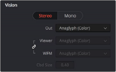
Monitoring controls for Stereo 3D
— Vision: Click a button to choose between Stereo, where both eyes can be displayed in the Viewer and output to video in a variety of different formats, and Mono, where only one eye is monitored in the Viewer and your video output interface.
— Out: A pop-up menu that provides different stereo viewing options for previewing stereo 3D signals in different ways. By default, this option is also linked to the Viewer display Internal Video Scope options. For detailed descriptions of each stereo 3D viewing mode, see the following section, “Stereo 3D Output Options.”
![]()
— Link button: When enabled, the Viewer and internal video scopes both use the Out pop-up menu’s option for stereo 3D viewing. When disabled, you can choose different stereo 3D viewing options for the Viewer and internal video scopes.
— Viewer: Lets you choose a stereo 3D viewing option for the Viewer.
— WFM: Lets you choose a stereo 3D viewing option for the internal video scopes.
— Cbd Size: If any stereo 3D viewing options are set to Checkerboard, this parameter becomes enabled, and lets you define the size of the checkerboard boxes, in pixels.
Dual 4:2:2 Y’CbCr stereoscopic video streams are output via HD-SDI on selected Blackmagic I/O devices when you turn on the ”Use left and right eye SDI output” checkbox on the Master Settings panel of the Project Settings. You can select either Side-by-Side or Line-by-Line output to be fed to your stereo-capable display, depending on your display’s compatibility.
Stereo 3D Output Options
Additionally, the Viewer and video scopes can be set to display both “eyes” in one of a variety of different modes.
— Side by Side: Displays both images side by side. Each eye is squeezed anamorphically to fit both eyes into the same resolution as the GUI viewer.
— Top and Bottom: Displays both images one over the other. Each eye is squeezed vertically to fit both eyes into the same resolution as the GUI viewer.
— Line by Line (Even/Odd): An interlaced mode where each eye is displayed on alternating lines. The thickness of the lines as seen in the Viewer depends on how zoomed in you are.
— Checkerboard: Displays both eyes via an alternating checkerboard pattern. This is an excellent mode for identifying regions of the image where there’s variation in color or geometry between the two eyes.
— Anaglyph (B/W): Each eye is desaturated and superimposed via Red/Cyan anaglyph to show the disparity between both eyes in different regions of the image. Left-eye divergence is red, and right-eye divergence is cyan. Regions of alignment between both eyes appear grayscale.
Anaglyph modes are useful for evaluating the geometric differences between both eyes, as well as for identifying the point of convergence (where both eyes align most perfectly) that places a region of the image at the screen plane.
Red/cyan color coding also identifies the direction of parallax. For any given feature, disparity such that red is to the right and cyan is to the left indicates positive parallax (backward projection away from the audience). Red to the left and cyan to the right indicates negative parallax (forward projection towards the audience).