< Previous | Contents | Next >
The Cintel Scanner Interface
![]()
Click on the ‘capture’ button in the UI toolbar at the top of the DaVinci Resolve screen to set the media page to control your Cintel scanner. Open DaVinci Resolve’s film scanner panel to set up, calibrate, and choose options for logging or scanning a selected range of the currently spooled roll of film. If you want more room for viewing the Cintel scanner controls, click the full height button that’s all the way to the right of the UI toolbar, and turn off the ‘metadata’ panel.
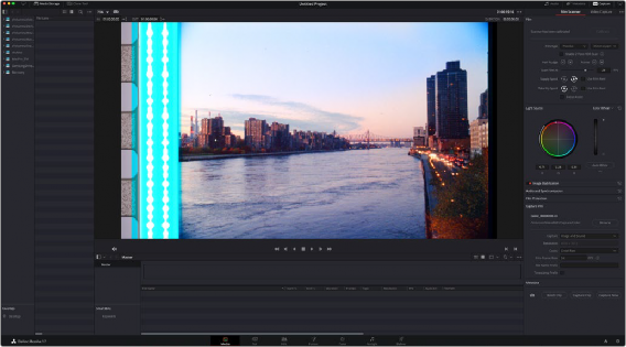
Cintel scanner controls in the Media page
— Transport Controls: The transport controls under the viewer, while similar in appearance to those used while in playback mode, now work to control the Cintel scanner. Additional controls appear for moving forward or backward a frame at a time.
— In and Out Controls: In Cintel Scanner mode, the In and Out buttons to the right of the transport controls define a range of the film roll from which to capture.
The follwing groups of settings appear to the right of the ‘media’ page viewer when in Cintel Scanner mode to scan clips from film into the media pool.
Calibration
This option lets you calibrate the optics of the scanner to eliminate optical blemishes or dust that cannot be removed. Please note that this feature does not remove dust from the film itself.
![]()
The calibration button can be used to help remove dust or small blemishes from the optics of your Cintel scanner.
— Calibrate: This button lets you eliminate light optical blemishes and dust from the optics of the Cintel scanner via digital calibration. While it’s recommended to “spray dust” the optics before scanning new material, it’s possible over time for some blemishes on the optics to be unremovable, in which case using the calibrate button will eliminate them from the scanned image.

TIP: Calibrate the optics with the skid plate installed and correctly aligned, as this assists with image stabilization and offers the best image quality.
TIP: Calibrate the optics with the skid plate installed and correctly aligned, as this assists with image stabilization and offers the best image quality.
TIP: Calibrate the optics with the skid plate installed and correctly aligned, as this assists with image stabilization and offers the best image quality.
The skid plate does not normally need to be removed for calibration, however, in cases where there is severe dirt, remove the skid plate, dust it, and then reinstall it. Use the ‘calibrate’ button before you load film into the scanner, while there’s nothing in the optical path, to remove any remaining optical blemishes or dust.
![]()
Film Type
These controls let you select the type of film you’re scanning, align the film with the sensor, and choose what speed you’re scanning at.
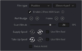
Film Type controls in the Media page

TIP: The scanner automatically detects whether the film is 35mm or 16mm.
TIP: The scanner automatically detects whether the film is 35mm or 16mm.
TIP: The scanner automatically detects whether the film is 35mm or 16mm.
— Film Type: Lets you choose what type of film you’re scanning. The choices are positive, negative, interpositive, and internegative. HDR scanning offers an improvement for all these film types. Select the reel type you’re scanning from 35mm 2, 3, and 4 perf, and 16mm.

NOTE: When scanning interpositive and internegative film, the increased density of the film requires slightly extended pulse durations from the light source. Normally, this does not affect the scan, however, a slight reduction in resolution may occur when scanning at above 12 frames per second. If you do notice a difference in resolution, simply reduce your scanning speed to 12 frames per second or less.
NOTE: When scanning interpositive and internegative film, the increased density of the film requires slightly extended pulse durations from the light source. Normally, this does not affect the scan, however, a slight reduction in resolution may occur when scanning at above 12 frames per second. If you do notice a difference in resolution, simply reduce your scanning speed to 12 frames per second or less.
NOTE: When scanning interpositive and internegative film, the increased density of the film requires slightly extended pulse durations from the light source. Normally, this does not affect the scan, however, a slight reduction in resolution may occur when scanning at above 12 frames per second. If you do notice a difference in resolution, simply reduce your scanning speed to 12 frames per second or less.
— Enable 2 Pass HDR Scan: Enables high dynamic range multi pass capture. It is important to perform an ‘auto black’ or ‘auto white’ on a frame with a wide dynamic range as it determines the high and normal exposure levels from your selected frame.
— Perf nudge: Used for making fine adjustments of the perf position relative to the scanner gate aperture. Command-J nudges up, while Command-L nudges down.
— Frame: These buttons are push and hold to activate. When on, the film is slowly advanced to move the frame up or down and when released the film stops in place. This is useful for aligning
the film frame with the scanner’s sensor. Using the ‘perf nudge’ and ‘frame’ buttons, you want to align the visible film frame so the bottom of the previous frame and the top of the next frame are just visible at the top and bottom of the viewer, and the current frame is centered vertically.
It’s important to make sure the image in the viewer is not zoomed in when you do this.
Command-Left Arrow on your keyboard moves the frame up, while Command-Right Arrow moves the frame down.
![]()
— Scan Speed: With adequate disk performance, you should be able to scan at 30 fps. However, if you’re scanning to a slow hard drive, you can reduce the scanning speed to a frame rate that’s suitable for your workstation without dropping frames.
— Supply: Sets the wind direction of the left-hand side feed spool. While auto-detection will prevent incorrect operation, you should manually configure the reel winding direction based on how each film roll is wound.
— Take up: Sets the wind direction of the right-hand side take up spool. While autodetection will prevent incorrect operation, you should manually configure the reel winding direction based on how each film roll is wound.
— Use Film Reel: Small film reels have a different weight and inertia compared to large film spools, and this can affect the transport system. Tick this box to switch to settings that offer improved stability for small film reels.
— Focus Assist: Enables luminance peaking on your scanner’s HDMI monitor output, plus the viewer inside DaVinci Resolve’s film scanner panel, which makes it easy to obtain optimum focus adjustments.
Light Source
These controls let you adjust the scanner’s light source to adjust the optimal Dmin, which is the minimum scanned signal value, plus the color temperature of the scanned material. Use the built in software scopes in DaVinci Resolve to help set your light source to its optimum level settings. Scopes can be opened in the Media page by choosing Workspace > Video Scopes > On. You can adjust these settings to make sure you’re not clipping image data during the scanning process.
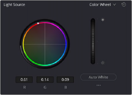
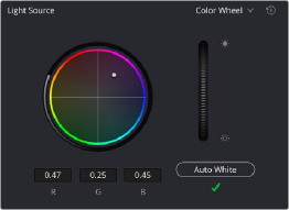
Light Source controls in the Media page showing the default uncalibrated status of the light source (left), and the status when calibration is successful (right)
— Light Source master wheel: The vertical light source master wheel is located next to the color wheel and adjusts the intensity of the light source used to illuminate the film, raising or lowering the RGB channels all at once. For typical negative film, this lets you adjust the black point of the film image, which is the darkest part of the image. In negative film, this in fact corresponds to the
highlights of the film image. Adjust the light intensity to sit just above the typical Dmin value of 95, as measured on the histogram of the video scopes, which guarantees that the highlights won’t be clipped by a Cineon-style LOG conversion. For positive film, simply adjust the master wheel so that no part of the signal is being clipped.

TIP: Whenever you change film type, gauge or enable HDR, the auto black/white calibration is reset. The status indicator under the auto black/white button reminds you to recalibrate the LED light source to help ensure the highest quality scans or inform you if any problems occur.
TIP: Whenever you change film type, gauge or enable HDR, the auto black/white calibration is reset. The status indicator under the auto black/white button reminds you to recalibrate the LED light source to help ensure the highest quality scans or inform you if any problems occur.
TIP: Whenever you change film type, gauge or enable HDR, the auto black/white calibration is reset. The status indicator under the auto black/white button reminds you to recalibrate the LED light source to help ensure the highest quality scans or inform you if any problems occur.
— Auto Black and Auto White button: Analyzes the current frame displayed in the viewer and does an automatic adjustment to set the black point for negative, or for print to set the white point. For positive film types, the ‘auto black’ button changes to ‘auto white’.
![]()
— RGB controls: By default, a color balance control lets you adjust all three color channels by varying amounts to alter the color temperature of the light source used to illuminate the film, while the adjusted R, G, and B values are displayed in three fields below. Optionally, you can choose to put this control into ‘color bars’ mode using the mode pop-up to the right of the ‘light source’ title bar, which changes this control to three vertical red, green, and blue color channel sliders.
Image Stabilization
These controls let you enable and disable as well as control image stabilization to eliminate vertical film hop.
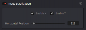
Image Stabilization controls in the Media page
— Image Stabilization enable/disable control: The dot to the left of the ‘image stabilization’ title bar lets you enable or disable your scanner’s hardware-based image stabilization altogether. While hardware stabilization is typically desirable when you have high quality perforations, you may want to turn this option off if the condition of the perforations is poor and you decide to use DaVinci’s software based stabilization instead.
When image stabilization is enabled, a horizontal X axis detection overlay is displayed in the viewer, highlighting the edge of the film perforation that will be used as the reference for stabilization.
This overlay is automatically hidden when recording. Image stabilization is enabled by default.
— Enable X and Y checkboxes: Enable X and enable Y lets you choose whether to use hardware image stabilization to fix horizontal gate weave and vertical gate hop respectively. If the results are unsatisfactory with both axes enabled, you can turn off the axis that’s causing issues with stabilization.
— Horizontal Position slider: Your Cintel scanner attempts to automatically place the stabilization detection overlay at the best location, with reference to the perforation shown on the currently loaded frame, for the best stabilization result.
You will notice a thin transparent line in the blue alignment overlay. For optimum stabilization, this line should touch the edge of the perforation. If the automatic positioning is not ideal, you can manually move the overlay to a more ideal position, either by dragging it in the viewer with your mouse, or by using the horizontal slider.
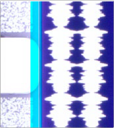
Ideal placement of the stabilization overlay should position the clear line in the alignment overlay on the edge of the perforation, as shown in the example image. With the overlay correctly positioned, this enables hardware stabilization of gate weave along the X axis.
![]()
Image stabilization automatically manages vertical gate hop when you select the ‘enable y’ checkbox. It needs no further adjustment and works in conjunction with horizontal stabilization.
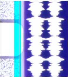
Adjusting the horizontal position of the stabilization overlay. In this screenshot, the overlay is not aligned with the edge of the perf.
Hardware stabilization control correctly positioned over a perforation in the viewer. The transparent stripe in the stabilization overlay touches the edge of the perforation.
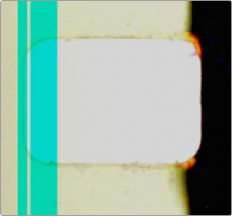
With the 16mm HDR skid plate installed, the stabilizer aligns automatically to the other side of the perforation to avoid interfering with the film image and improve horizontal stability. When using a ‘non-HDR’ 16mm skid plate, it functions the same as the 35mm skid plate.
To closely check the results of your stabilization settings before capturing, set the viewer to full resolution. Simply click on the options settings at the top right corner of the viewer and select ‘Full Resolution Preview’ from the menu. This setting does not affect the stabilization feature, but enables the best possible preview so you can monitor how well it is performing.
It’s worth mentioning that this setting will remain set until you change it back to your previous setting. Full resolution is very GPU intensive and may result in some frame lag. For best performance, turn full resolution off after checking stabilization.
Film Protection
![]()
These controls are intended to allow delicate film to be handled gently by the Cintel Scanner. Fast acceleration and shuttle speeds can be hard on archival footage, so it’s recommended to lower both of these sliders from their defaults whenever you’re scanning older film.
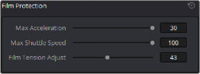
The ‘Acceleration’ and ‘Shuttle Speed’ sliders should be lowered when scanning older, delicate archival film.
— Max Acceleration: Sets the maximum change in speed to increase or decrease by 5-30 fps per second.
— Max Shuttle Speed: Changes the speed of shuttling from one section of film to another between 1–100 frames per second for 35mm film, and between 1–200 frames per second for 16mm film.
— Film Tension Adjust: If your Cintel Scanner has sprocket wheels, this setting gives you the ability to adjust the amount of tension applied to 35mm film. For example, when loading delicate archival film, or compensating for film shrinkage. There is no possible way you can damage the film with the ‘film tension adjust’ setting. The adjustment values are very small and only gentle changes are all that’s required to prevent sprocket picking.
If your Cintel Scanner has capstans, sprocket picking cannot occur so this setting is disabled.
Editing Capture Info Metadata
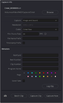
When DaVinci Resolve is used in conjunction with Cintel Scanner, a set of capture metadata fields appears at the bottom of DaVinci Resolve’s film scanner panel. The ‘capture info’ panel has editable metadata fields that describe capture properties such as where to save files, the type of codec, frame rate, and the format of file names. This metadata is attached to your clips and can be read on the media page.
Before you begin scanning, you may want to adjust some of the project settings.
![]()
The ‘capture info’ panel lets you specify metadata for your scanned clips.
— Capture Location: Before you begin a film scanning session, scroll down to the ‘capture info’ section of DaVinci Resolve’s film scanner panel to make sure the scanned files are being saved to the directory and volume where you want them. Click the ‘browse’ button and choose a location from the file destination dialog. It’s good to do this first, as this step is easy to forget.
— Capture: When you have a Cintel Audio and KeyKode Reader fitted, this menu gives you options for ‘audio only’ so no images will be captured, or ‘image and sound’. Alternatively, you can capture ‘image only’ if audio is not important.
— Resolution: The resolution of the capture files depends on the source film format so this field cannot be edited.
— Codec: DaVinci Resolve selects the ‘Cintel Raw’ codec for lossless compression by default, or you can choose ‘Cintel Raw 3:1’ for even smaller file sizes.
— Film Frame Rate: Specify the frame rate that the film was originally shot at. DaVinci Resolve automatically adjusts the timeline frame rate based on this value. This setting is unrelated to capture or transport speeds.
When using the optional Audio and KeyKode Reader accessory to scan audio, the reader will automatically adjust for frame rate to maintain an overall sample rate of 48kHz. Timecode output is supported for 24, 25 and 30 fps, and for other frame rates no timecode signal is outputted.
— File Name Prefix: Prefix to help identify the scan. This can be the name of your project, such as the title of the film you are scanning.
— Timestamp Prefix: Select this checkbox to prefix your scans with a timestamp as well as the ‘file name prefix’ you specified. Your clips will be saved to independent sub-folders in the destination folder. This checkbox is selected by default.

NOTE: If you don’t make capture names unique with the timestamp prefix and the files go into the same location, this could potentially overwrite files.
NOTE: If you don’t make capture names unique with the timestamp prefix and the files go into the same location, this could potentially overwrite files.
NOTE: If you don’t make capture names unique with the timestamp prefix and the files go into the same location, this could potentially overwrite files.