< Previous | Contents | Next >
The Fairlight Timeline and Mixer showing the same track selection, A1, A3, and A5, with A3 as the active track.
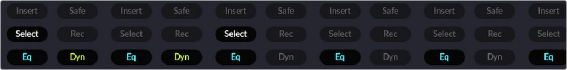
Channel extension buttons on the optional HDMI monitor showing illuminated Select Buttons for tracks A1 and A5.
Fairlight Desktop Console
Now that you are familiar with the general layout, types of controls, modes, and other options in the Fairlight Desktop Console, you are ready to take a more detailed look at the different areas of operation and how everything works together. One primary concept to keep in mind is that the Fairlight Desktop Console is designed specifically to control the DaVinci Resolve Fairlight page. Therefore, the better you understand the Fairlight page, the more proficient you’ll be with your console.
![]()
Please refer to previous Fairlight chapters for detailed information on the software interface, tools, functions, and audio workflows. Meanwhile, this section will give an overview of the entire Fairlight Desktop Console and focus in-depth on unique features and functions that go beyond the standard keyboard and mouse options in the Fairlight page.
Control Buttons
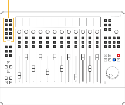
The twelve control buttons in the upper-left corner of the Desktop Console offer fast access to all of the mixing parameters available in the Fairlight Mixer, without the need to grab your mouse. Each control button maps a different set of mixing parameters to the upper section of the channel strips. These parameter control sets are identical to the parameter controls in the corresponding UI windows
accessible in the Fairlight Mixer. Additionally, if you are using an HDMI monitor with your Desktop Console, the active control set parameters on the monitor screen are highlighted in blue text.
The control sets include the LCD screens, knobs, and SEL buttons and work collectively for Focus mode operations. The control area defaults to the standard operational strip mode whenever there are no control buttons active.
Control buttons that assign control sets to the adjacent Select buttons, knobs, and LCDs
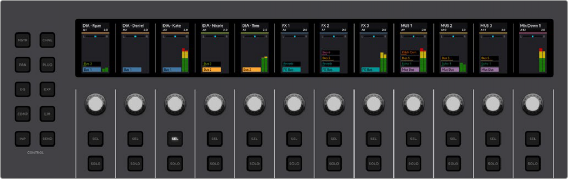

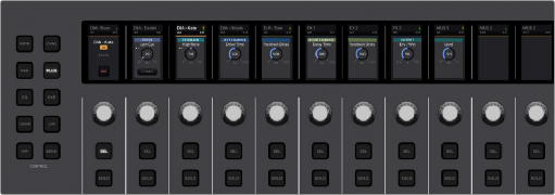
NOTE: In each of the following control set examples, track A3 DIA - Kate is the active track. You can easily identify the active track because the track-based Focus mode control sets always display the active track’s name, number, and color in the first channel strip’s LCD.
NOTE: In each of the following control set examples, track A3 DIA - Kate is the active track. You can easily identify the active track because the track-based Focus mode control sets always display the active track’s name, number, and color in the first channel strip’s LCD.
NOTE: In each of the following control set examples, track A3 DIA - Kate is the active track. You can easily identify the active track because the track-based Focus mode control sets always display the active track’s name, number, and color in the first channel strip’s LCD.
Default mode where SEL is Select button, knob controls Pan, and LCD shows channel info for each of the 12 channel strips.
![]()
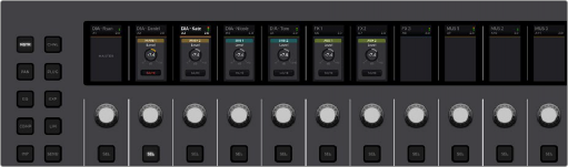
Master control set mapping shows MAIN 1, MAIN 2, SUB 1, SUB 2, AUX 1, and AUX 2
![]()
Knob controls update in realtime as they are adjusted. SEL switches illuminate when enabled and the label on the corresponding user interface switch in the LCD turns red. The Channel controls from left to right are; Active Track DIA - Kate A3, Path Trim, High Pass Filter Frequency, Low EQ Gain, Low Mid Gain, High Mid Gain, High Gain, Low Pass Filt Frequency, Compressor Threshold, Lmiter Threshold, Pan Left/Right and Front/Back. These controls are also available in the associated Focus mode control sets.
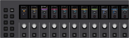
Page 1 of the Channel control set mapping
![]()
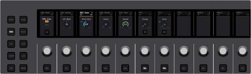
Pan control set mapping includes all parameters in the Fairlight Pan window.
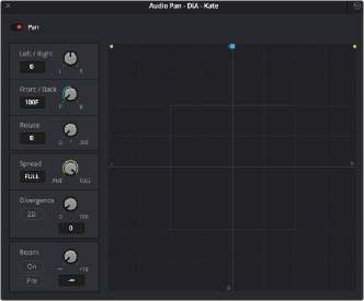
Pan window available in the Fairlight page Mixer
![]()
Pan control set visual feedback in optional HDMI monitor
![]()
Hold Plug and press User 1 to User 6 to choose a different plugin slot for focus. This also opens the corresponding Plugin window in the Fairlight page interface.
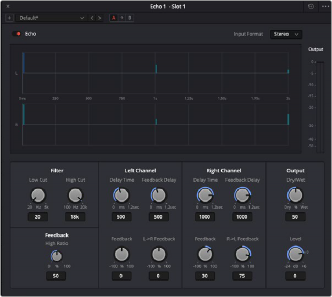
Echo control set mapping
Echo Plugin window that mirrors the Plugin control set on the
Fairlight Desktop Console
![]()
![]()
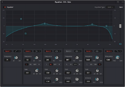
Hold CTL and press EQ to switch to Page 2.
This EQ control set focuses on the High Pass and Low Pass filters on Bands 1 and 6, and the corresponding SEL switches toggle the filters ON/OFF or shape. Press EQ again to return to Page 1 and repeat as needed to toggle between Page 1 and Page 2. The EQ control set mirrors all of the parameter controls available in the Fairlight EQ window.
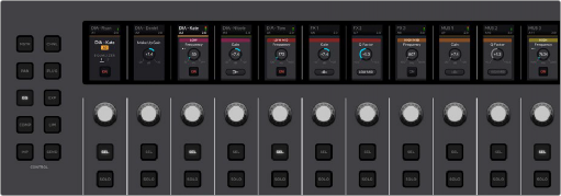
EQ control set Page 1 with controls for Bands 2-5
EQ control set Page 2 with controls for the filters on Bands 1 and 6
![]()
Fairlight EQ controls available via the Fairlight Mixer
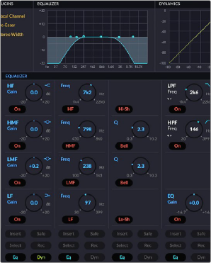
EQ control set visual feedback in optional HDMI monitor
![]()
the order they appear on the Dynamics window. From left to right in Channel Strips 2-7 the controls are: Threshold, Range, Ratio, Attack, Hold, and Release.
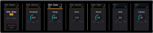
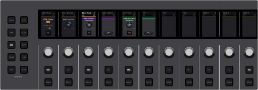
Fairlight Expander/Gate control set
![]()
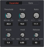
Fairlight Expander/Gate parameters in the Dynamics windows
![]()
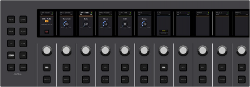
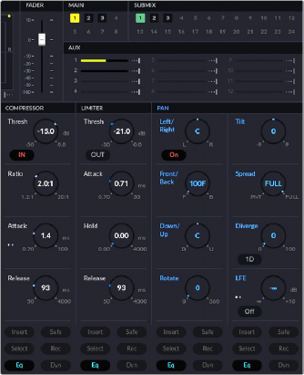
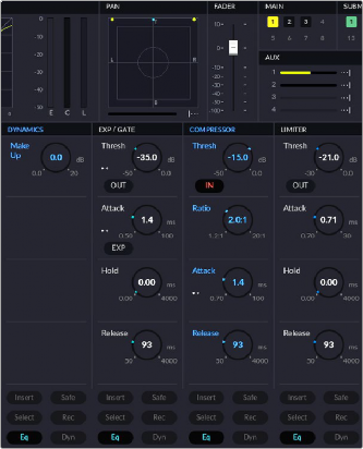
Fairlight Dynamics window, Compressor controls
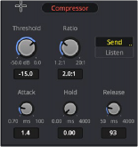
Fairlight Compressor controls available via the Fairlight Mixer
![]()
![]()
Fairlight Dynamics window, Limiter controls
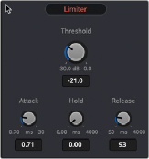
Fairlight Limiter controls
available via the Fairlight Mixer
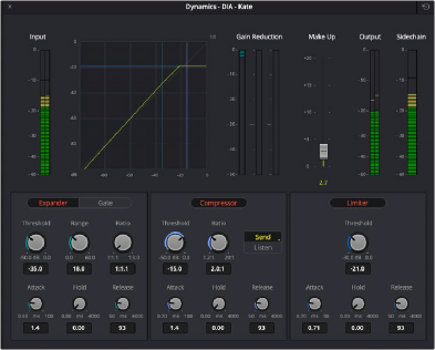
Fairlight Dynamics Window, which includes Expander, Gate, Compressor, and Limiter.
![]()
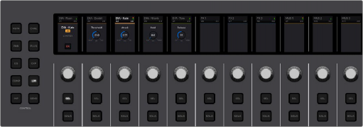
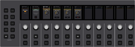
Compressor control set visual feedback in optional HDMI monitor. All Focus mode dynamics parameters grouped together in
one section of the HDMI data screen. The active dynamics controls are highlighted in blue.
![]()
Input control set mapping
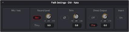
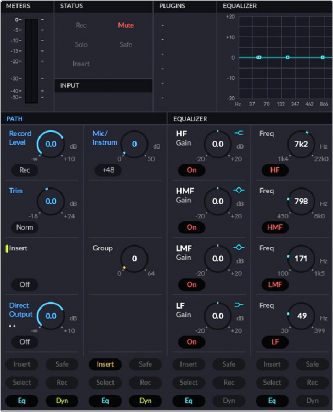
Path Settings available in the Input section of the Fairlight Mixer
Input control set with Path visual feedback in optional HDMI monitor
![]()